Non-contact power transmission device

Inactive Publication Date: 2012-12-27
PANASONIC CORP
View PDF3 Cites 83 Cited by
  • Summary
  • Abstract
  • Description
  • Claims
  • Application Information

AI Technical Summary

Benefits of technology

[0015]The present invention starts a detection process for a metal foreign object before starting normal power transmission and can thus detect a metal foreign object at an early stage.

Problems solved by technology

This may heat a metal foreign object during, for example, the verification period.

Method used


Image

  • Non-contact power transmission device
  • Non-contact power transmission device
  • Non-contact power transmission device

Examples


Embodiment Construction

[0021]A contactless charging apparatus according to one embodiment of the present invention will now be described with reference to FIGS. 1 and 5.

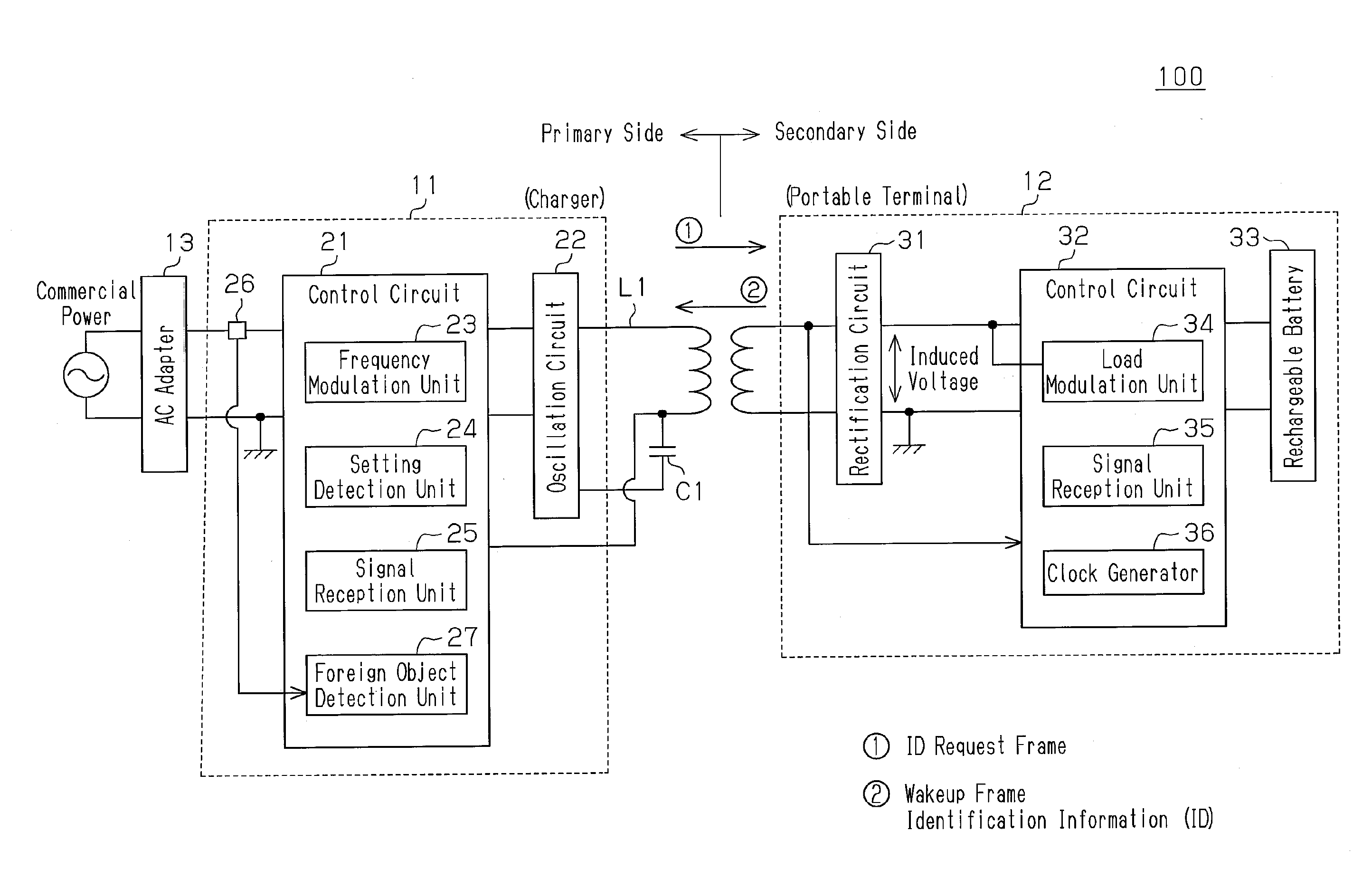
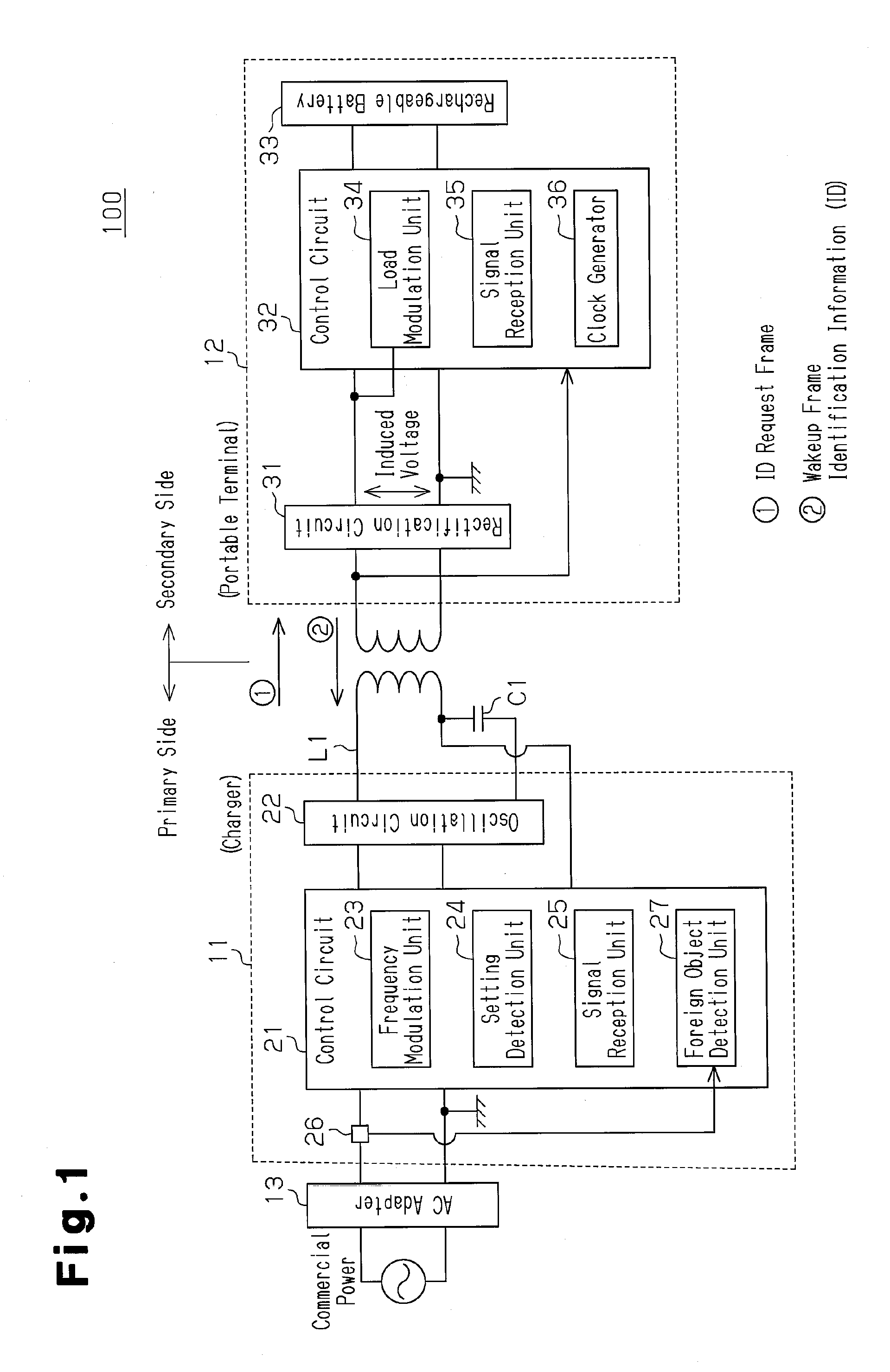
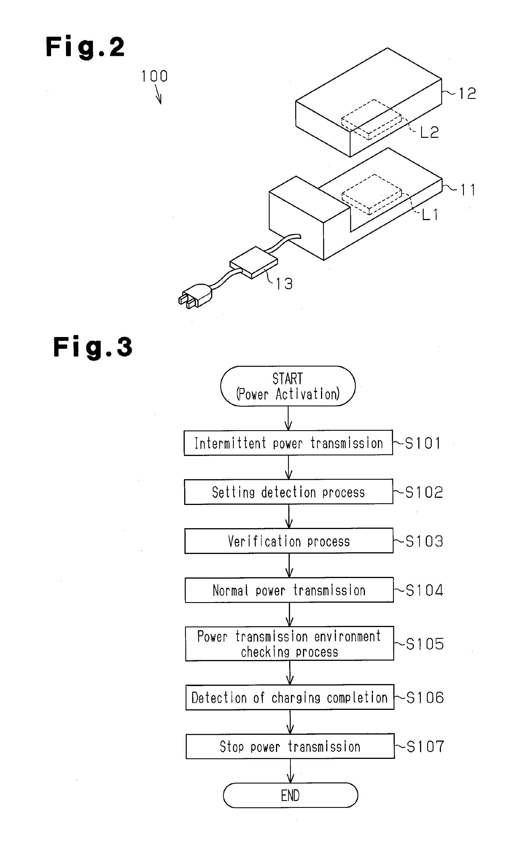
[0022]Referring to FIG. 2, a contactless charging apparatus 100 includes a power transmitting electronic device and a power receiving electronic device. The power transmitting electronic device is, for example, a charger 11, and the receiving side electronic device is, for example, a portable terminal 12. The charger 11 is connected, for example, to a commercial power (AC) via an AC adapter 13. The AC adapter 13 converts commercial power into DC power. The charger 11 converts the converted DC power back to AC power and transmits the converted AC power in a contactless manner to the portable terminal 12, which is set on the charger 11. The portable terminal 12 uses the transmitted AC power to at least charge the rechargeable battery incorporated in the portable terminal 12. Power transmission from the charger 11 to the portable terminal 12 ...


PUM


Abstract

A portable terminal is activated when receiving verification power transmitted in a contactless manner from a charger using electromagnetic coupling between the charger and the portable terminal. The portable terminal sends an electrical signal (wakeup frame) indicating activation immediately after being activated to the charger. Reception of the wakeup frame triggers the power transmitting device to start a verification process on the power receiving device and perform a detection process for a metal foreign object. After authentication is established, the charger transmits normal power to the portable terminal.

Description

RELATED APPLICATIONS[0001]This application is the U.S. National Phase under 35 U.S.C. §371 of International Application No. PCT / JP2011 / 057763, filed on Mar. 29, 2011, which in turn claims the benefit of Japanese Application No. 2010-096126, filed on Apr. 19, 2010, the disclosures of which Applications are incorporated by reference herein.TECHNICAL FIELD[0002]The present invention relates to a contactless power transmission device that transmits power in a contactless manner between a power transmitting electric device and a power receiving electric device through electromagnetic coupling.BACKGROUND ART[0003]As described in, for example, patent document 1, a contactless power transmission apparatus of the prior art includes a power transmitting electric device, such as a charger (cradle), and a power receiving electric device, such as a cellular phone. The power transmitting electric device is electromagnetically coupled to the power receiving electric device to transmit power in a c...

Claims


Application Information

Patent Timeline
Patent Type & Authority Applications(United States)
IPC IPC(8): H02J17/00H02J7/00
CPCH01M10/425H01M10/44H01M2010/4278H02J7/025H02J2007/0001H01M10/46H02J7/00045Y02E60/10H02J7/0044H02J50/80H02J50/90H02J50/12H02J50/60
Inventor MATSUMOTO, TAKAOKIISAKA, ATSUSHISUZUKI, KAZUHIROKADA, KYOHEIKANAKUBO, YOSHIHIDENAGATAKE, YOHEIKIHARA, HIDEYUKI
Owner PANASONIC CORP
Why Eureka
Try Eureka