
In-circuit memory array bit cell threshold voltage distribution measurement

a technology of in-circuit memory array and threshold voltage, which is applied in the direction of digital storage, instruments, and architectures with single central processing units, etc., can solve the problems of long test time, complicated external voltage and timing control, and the test platform must be able to opera

Inactive Publication Date: 2001-05-01
PROGRESSIVE SEMICON SOLUTIONS
View PDF19 Cites 88 Cited by
  • Summary
  • Abstract
  • Description
  • Claims
  • Application Information

AI Technical Summary

Benefits of technology

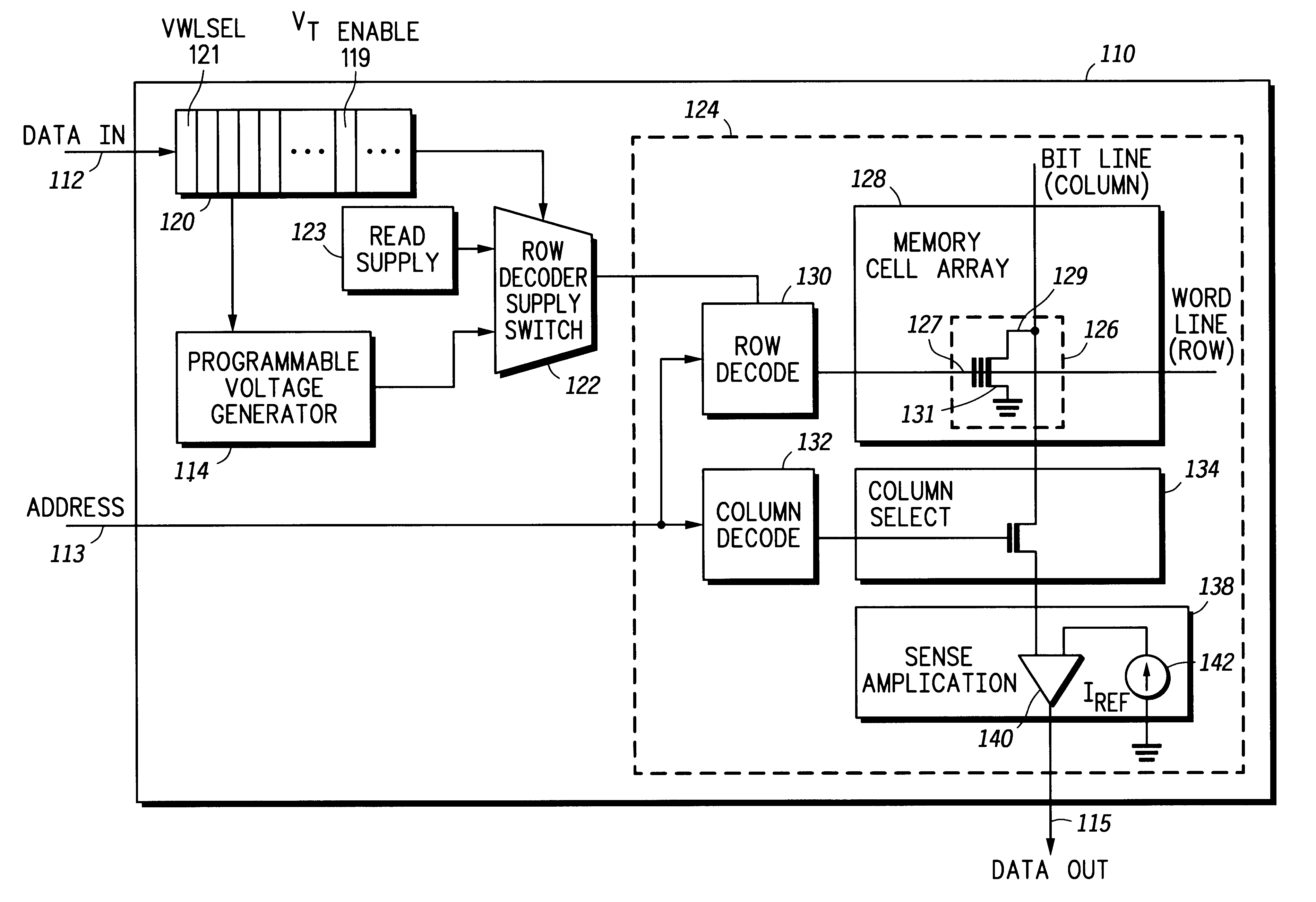
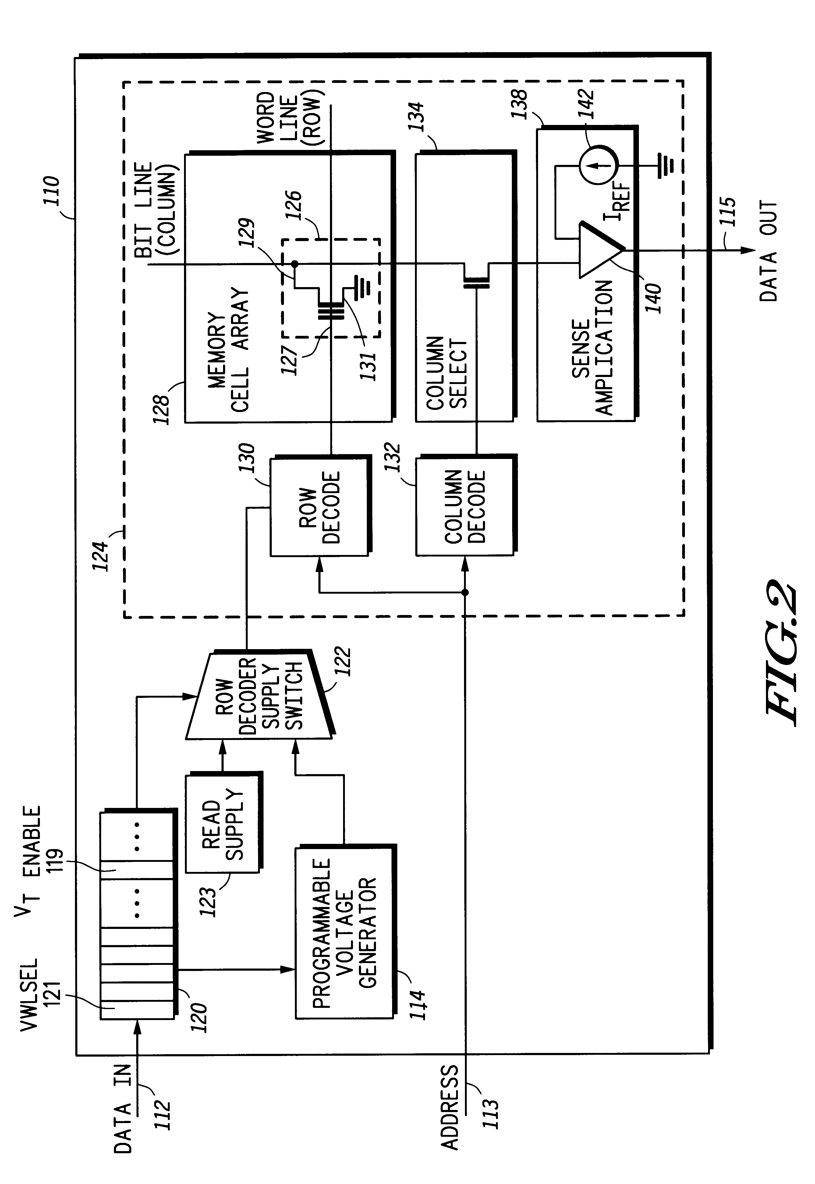
FIG. 6 is a flow chart showing the method according to another embodiment of the present invention for the detection of imminent failures. One advantage of the present invention is that imminent failures of a memory cell array can be detected early, for example, by a customer, without the use of external test platforms. The non-volatile memory integrated circuit and method of operation according to the present invention is suitable for self test in highly parallel environments and provides for early imminent failure detection. FIG. 6 illustrates an embodiment wherein, in the test mode, imminent failure of the NVM 110 is detected. The operational power supply, illustrated as the read supply 123, is selected and applied to the NVM 110 and, at block 500, a first set of data is read from the array of bit cells after applying the operational power supply to the NVM 110. At block 502 the test mode is configured for the NVM 110 including selecting and applying the test power supply to the NVM 110. At block 504 the word line voltage is set to an imminent failure voltage value and then, at block 506, the array of bit cells is re-read giving a second set of data from the array of bit cells. At block 508 the first set of data is compared to the second set of data. A decision is made at decision block 510 to determine if an imminent failure is indicated based on the comparison of the first set of data to the second set of data, for example, indicating an imminent failure possible at block 512 if the comparison of the first set of data and the second set of data shows that the data does not match.

Problems solved by technology

A disadvantage of both prior methods is that the test platform must be able to sweep a precisely controlled input voltage and, in the case of the first method, measure small bit cell currents.
Typical measurement of current Flash EEPROM array threshold voltage distributions require complicated external voltage and timing control to collect using existing production test platforms.
For example, existing production test platforms require synchronization of devices under test, complex control codes, and intelligent test platforms, resulting in long test times and are not suitable for highly parallelized test environments due to the high pin count of the devices under test.
Other issues to consider in testing microcontrollers with embedded non-volatile memory (NVM) on a single site tester include decrease data retention and worse gate / drain stress results after program / erase cycling and identification of latent program / erase endurance failures for parts with high endurance specifications.

Method used


Image

  • In-circuit memory array bit cell threshold voltage distribution measurement
  • In-circuit memory array bit cell threshold voltage distribution measurement
  • In-circuit memory array bit cell threshold voltage distribution measurement

Examples


Embodiment Construction

[OF THE PREFERRED EMBODIMENTS]

The following is intended to provide a detailed description of an example of the invention and should not be taken to be limiting of the invention itself. Rather, any number of variations may fall within the scope of the invention which is defined in the claims following the description.

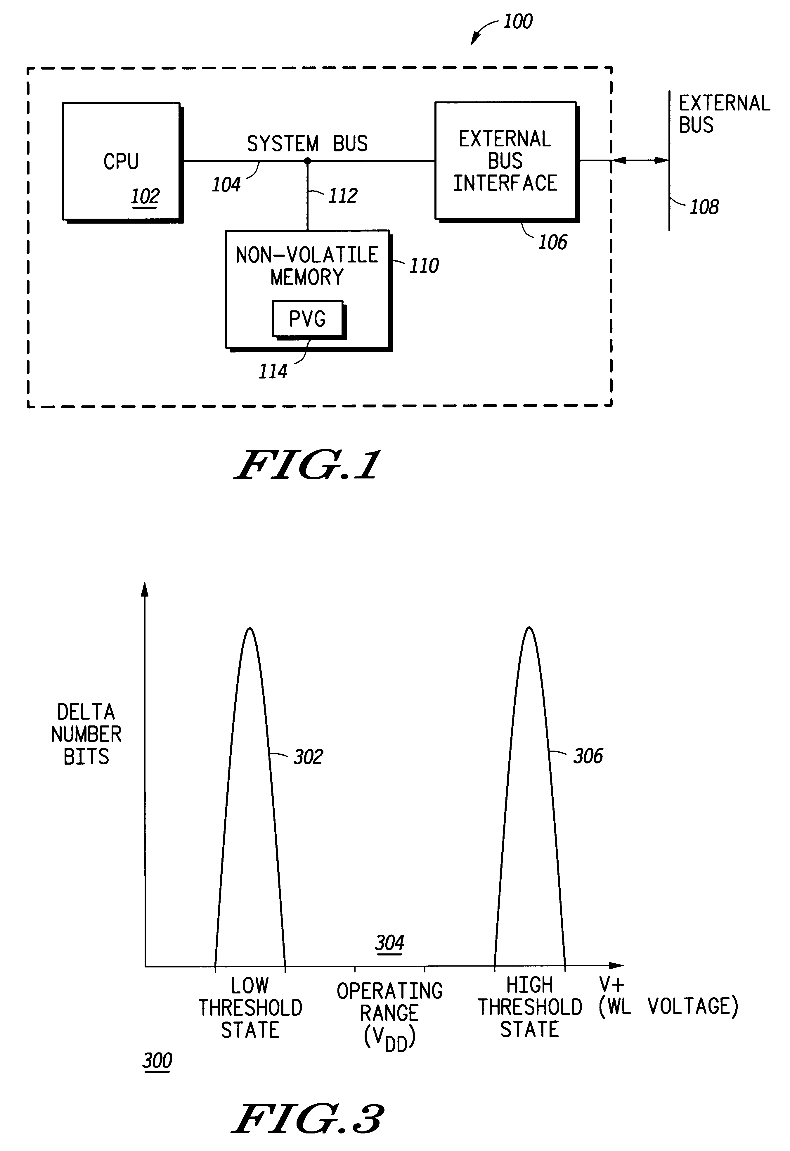
FIG. 1 is a functional block diagram of a microcontroller 100 including an embedded non-volatile memory (NVM) 110 module, the NVM 110 module further including an on-chip programmable voltage generator (PVG) 114. The microcontroller 100 further includes a central processing unit (CPU) 102 connected to the NVM 110 module through a system bus 104. An external bus interface 106 is connected to the NVM 110 and CPU 102 through the system bus 104 and is utilized to connect external devices such as, for example, I / O devices (not shown) through an external bus 108.

The foregoing components and devices are used herein as examples for sake of conceptual clarity. As, for examples, CP...


PUM


Abstract

An apparatus and method for operating a non-volatile memory including an array of bit cells. A selection is made between an operational power supply and a test power supply, the test power supply being on-chip programmable. The non-volatile memory is operated in a operational mode if the operational power supply is selected, and in a test mode if the test power supply is selected.

Description

1. Field of the InventionThe present invention relates to non-volatile memory systems and, more particularly, to a memory system including an in-circuit or on-chip technique to measure threshold voltages of bit cells in the non-volatile memory system.2. Description of the Related ArtMeasurement of threshold voltages of bit cells in NVM systems has typically included using external production test platforms and, for example, measuring the current / voltage characteristics of bit cells in flash memory by sweeping an input voltage and measuring bit cell voltage on a pin. Another method for measurement of threshold voltages of bit cells in NVM systems includes using external production test platforms and, for example, measuring the current / voltage characteristics of bit cells and comparing the bit cell current / voltage characteristics against an internal reference by sweeping an input voltage and reading a digital data output. A disadvantage of both prior methods is that the test platform ...

Claims


Application Information

Patent Timeline
IPC IPC(8): G11C5/14G11C29/50G11C29/12G11C29/04G01R31/28G06F12/16G06F15/78G11C16/02G11C16/06G11C29/00G11C29/02
CPCG11C5/147G11C29/12G11C29/50G11C29/50004G11C16/04G11C29/00
Inventor EGUCHI, RICHARD KAZUKICHRUDIMSKY, DAVID WILLIAMJEW, THOMAS
Owner PROGRESSIVE SEMICON SOLUTIONS
Learn More