Belt retractor for a vehicle safety belt

a technology for vehicle safety and belt retractor, which is applied in the direction of safety belts, vehicular safety arrangments, pedestrian/occupant safety arrangements, etc., can solve the problems of limited relative rotation between the belt spool and the locking disc, and no safety belt can be withdrawn from the belt retractor, so as to achieve the effect of increasing the permissible angle range and increasing strength

Active Publication Date: 2006-07-27
TRW AUTOMOTIVE GMBH
View PDF9 Cites 16 Cited by
  • Summary
  • Abstract
  • Description
  • Claims
  • Application Information

AI Technical Summary

Benefits of technology

[0005] To solve this problem, in accordance with the invention a detent is provided, which is arranged movably in the belt spool and can prevent a rotation of the locking disc relative to the belt spool as a function of its position. The adjustable arrangement of the detent opens up a variety of new construction possibilities. In an embodiment which is intended to make possible just one single revolution of the belt spool relative to the control ring, the permissible angle range can be increased compared with constructions according to the prior art by the angle range which the detent assumes in the prior art. In addition, it is not necessary to provide a groove in the locking disc for the detent extending over approximately 360 degrees, so that a higher strength results. When more than one revolution of the belt spool relative to the locking disc is desired, the detent can be moved via an intermediate position which is assumed for example after approximately one revolution, fully into its operating position so that it becomes effective at the end of the second revolution of the belt spool relative to the locking disc. The intermediate position can either be brought about by a suitably developed cam or by a spacer.

Problems solved by technology

When the locking disc is blocked against a rotation in the unwinding direction of the safety belt in the frame, initially no safety belt can be withdrawn from the belt retractor.
It is also known that the extent of the relative rotation between the belt spool and the locking disc is to be limited.

Method used


Image

  • Belt retractor for a vehicle safety belt
  • Belt retractor for a vehicle safety belt
  • Belt retractor for a vehicle safety belt

Examples


first embodiment

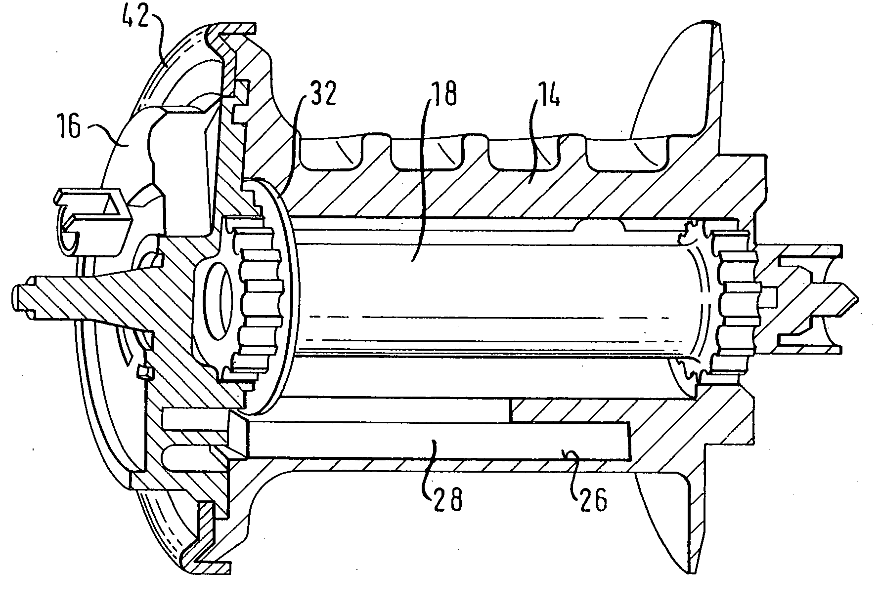
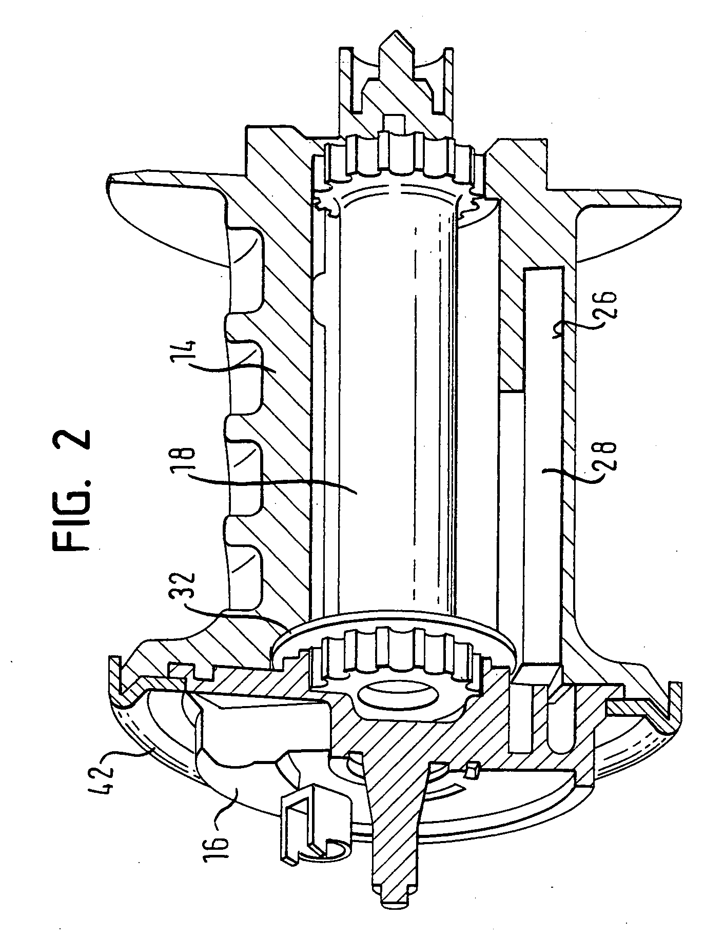
[0034] With the aid of FIGS. 2 to 8, the belt retractor is now described. The belt spool 14 is provided with a mounting 26, in which a detent 28 is displaceably arranged. The detent 28 has the form of a pin with a rectangular cross-section (see also FIG. 5) and is provided at an axial end with a cam 30. The detent 28 is displaceably arranged in the mounting 26, the cam 30 being arranged towards the locking disc 16.

[0035] To move the detent 28 between a position of rest which is illustrated in FIGS. 2, 3 and 7, and an operating position which is illustrated in FIGS. 4 and 8, a control ring 32 is used, which is provided with a control link 34. The control link 34 is constructed here as a ramp surface, running obliquely, on a shoulder of the control ring 32, which is bent from the plane of the ring by approximately 90 degrees. The control link 34 therefore acts in axial direction in relation to the control ring.

[0036] The control ring 32 is arranged on the locking disc 16 so as to be ...

sixth embodiment

[0047] In FIGS. 22 to 24, the belt retractor is shown. The difference from the previous embodiment consists in that a stop element 60 is provided, on which the cutting element 52 comes into abutment, after it has carried out just one revolution relative to the belt spool. The stop element 60 is constructed as an insert piece or impression piece of hardened metal, which has such a strength that it can not be cut by the cutting element 52. In FIG. 24, the position of the locking disc 16 with the cutting element 52 can be seen in the initial position. With a relative rotation of the belt spool relative to the locking disc 16, the detent 28 slides from the cutting element 52 (via a transition section 62 formed hereon) onto the end face of the locking disc 16. After dipping into the recess 36, the detent 28 arrives in abutment against the detent surface 38. Thereby, the cutting element 52 is moved. The relative rotation between the belt spool 14 and the locking disc 16 is limited after a...


PUM


Abstract

A belt retractor for a vehicle safety belt has a frame, a belt spool for the safety belt which is rotatably arranged in the frame, a locking disc which is arranged on the belt spool and is connected therewith through an energy absorption element, and a blocking mechanism which allows to block the locking disc against a rotation in the unwinding direction of the safety belt in the frame. A detent is provided which is movably arranged in the belt spool and can prevent a rotation of the locking disc relative to the belt spool as a function of its position.

Description

[0001] The invention relates to a belt retractor for a vehicle safety belt, with a frame, a belt spool for the safety belt which is arranged rotatably in the frame, a locking disc which is arranged on the belt spool and is connected therewith by means of an energy absorption element, and a blocking mechanism by means of which the locking disc can be blocked against a rotation in the unwinding direction of the safety belt in the frame. BACKGROUND OF THE INVENTION [0002] When the locking disc is blocked against a rotation in the unwinding direction of the safety belt in the frame, initially no safety belt can be withdrawn from the belt retractor. This ensures that a vehicle occupant who is wearing the safety belt, takes part as early as possible in a vehicle deceleration. In order to prevent the forces exerted here onto the vehicle occupant by the safety belt from assuming undesirably high levels, the energy absorption element makes possible a relative rotation between the belt spool ...

Claims


Application Information

Patent Timeline
Patent Type & Authority Applications(United States)
IPC IPC(8): B65H75/48B60R22/28B60R22/38B60R22/34B60R22/36
CPCB60R22/3413B60R2022/283B60R2022/287
Inventor BLUM, HERBERTGENTNER, BERNDKIELWEIN, THOMAS
Owner TRW AUTOMOTIVE GMBH
Why Eureka
Try Eureka