Projection screen and projection display

a projection screen and projection display technology, applied in the field of projection screens, can solve the problems of difficult mold making of unit prism molds, image light loss, and inability to reduce, so as to increase the allowable angle of incidence, reduce surface brightness or contrast, and increase the angle of incidence. the effect of the angle of inciden

Inactive Publication Date: 2006-07-04
DAI NIPPON PRINTING CO LTD
View PDF12 Cites 17 Cited by
  • Summary
  • Abstract
  • Description
  • Claims
  • Application Information

AI Technical Summary

Benefits of technology

[0013]The present invention has been accomplished in the light of the above-described drawback in the background art. An object of the present invention is to provide, by increasing the allowable range of the angle of incidence of imaging light that is a range in which imaging light loss due to the production of stray light or the like is not caused, a projection screen and a projection display that can display, without undergoing lowering of surface brightness or contrast, an image with high quality comparable to an image that is obtained when imaging light is projected on a projection screen almost vertically from an imaging light source.
[0026]According to the present invention, in a projection screen on which imaging light is obliquely projected from a projection optical system that is placed at the rear side of the projection screen, by providing a total reflection prism lens having a plurality of unit prisms on its back surface on which imaging light is incident, it is possible to correct, only on the incident side (back surface side), the optical axis of imaging light obliquely projected from the projection optical system and let the imaging light emerge toward the viewer's side. In the present invention, the unit prisms are made to have apical angles varying with the position on the screen plane. Specifically, for example, in the case where the unit prisms extend concentrically around the center of the concentric circles that is not on the screen plane, the apical angles of the unit prisms are varied within a certain angle range (e.g., 30° or more and 45° or less) so that the apical angles on the side distant from the center of the concentric circles are greater than the apical angles on the side close to the center of the concentric circles. Namely, in the area on the side close to the projection optical system in which the angle of incidence of imaging light is small, the unit prisms are made to have smaller apical angles, while in the area on the side distant from the projection optical system in which the angle of incidence of imaging light is great, the unit prisms are made to have greater apical angles. For this reason, it is possible to increase the allowable range of the angle of incidence of imaging light that is a range in which imaging light loss due to the production of stray light or the like is not caused, and is thus possible to obtain a projection screen and a projection display that can display, without undergoing lowering of surface brightness or contrast, an image with high quality comparable to an image that is obtained when imaging light is projected on a projection screen almost vertically from a projection optical system.
[0027]Further, according to the present invention, by providing, on the total reflection prism lens, a first apical-angle-fixed area in which the unit prisms have apical angles fixed at a predetermined first angle, a second apical-angle-fixed area whose location is different from that of the first apical-angle-fixed area and in which the unit prisms have apical angles fixed at a predetermined second angle that is different from the first angle, and an apical-angle-varying area that is situated between the first and second apical-angle-fixed areas and in which the unit prisms have apical angles varying between the first and second angles with the position on the screen plane, it is possible to vary the apical angles of the unit prisms of the total reflection prism lens not over the entire screen plane but only partially. By this, it becomes possible to easily make a mold for use in the molding of the total reflection prism lens, and a projection screen and a projection display, both capable of ensuring high image quality, can thus be obtained more inexpensively.
[0028]Furthermore, according to the present invention, by providing, in the apical-angle-varying area on the total reflection prism lens, a first apical-angle-varying part in which the unit prisms have apical angles that vary as only the angle between the first plane of the unit prism and the screen plane varies, with the angle between the second plane of the unit prism and the screen plane remaining unchanged, and a second apical-angle-varying part and a third apical-angle-varying part between the first apical-angle-varying part and the first apical-angle-fixed area and between the first apical-angle-varying part and the second apical-angle-fixed area, respectively, in which the unit prisms have apical angles that vary as both the angle between the first plane and the screen plane and the angle between the second plane and the screen plane vary, it is possible to further make the boundaries between the above areas appear unclear, and is thus possible to attain higher image quality.
[0029]Furthermore, according to the present invention, by making the first plane of each unit prism have a draft angle of 0° or more to the perpendicular (normal) to the screen plane, it is possible to prevent production of stray light, and is thus possible to prevent imaging light loss. In addition, in this case, since the mold for use in the molding of the unit prisms includes no reverse tapered portions, it is easy to make the mold, and, moreover, the unit prisms can be easily released from the mold in the lens molding process.
[0030]Furthermore, according to the present invention, by making the surface roughness of the first planes of the unit prisms uniform over the entire screen plane, it is possible to prevent occurrence of unevenness in an image on the screen plane so that a high-quality image can be viewed.

Problems solved by technology

The drawback of a projection display of this mode has been that since it requires a depth nearly equal to that of a conventional CRT projection display, it cannot be made smaller.
Therefore, there has been such a problem that part of imaging light incident on the plane of incidence 311a of each unit prism 311 is totally reflected at the plane of total reflection 311b of the unit prism 311 and is then reflected again at the plane of incidence 311a to become stray light, causing imaging light loss.
Further, there has been such a problem that, if the planes of incidence 311a of the unit prisms 311 are reverse tapered, it becomes difficult to make a mold for use in the molding of the unit prisms 311 and also to release the unit prisms from the mold in the lens molding process.
Thus, the conventional projection screens have the following drawback: since they have narrow allowable ranges of the angle of incidence of imaging light and tend to cause imaging light loss due to the production of stray light or the like, they easily undergo lowering of surface brightness or contrast.

Method used


Image

  • Projection screen and projection display
  • Projection screen and projection display
  • Projection screen and projection display

Examples


first embodiment

[0054]First of all, a projection screen according to the first embodiment of the present invention and a projection display comprising it will be described with reference to FIGS. 1 to 10.

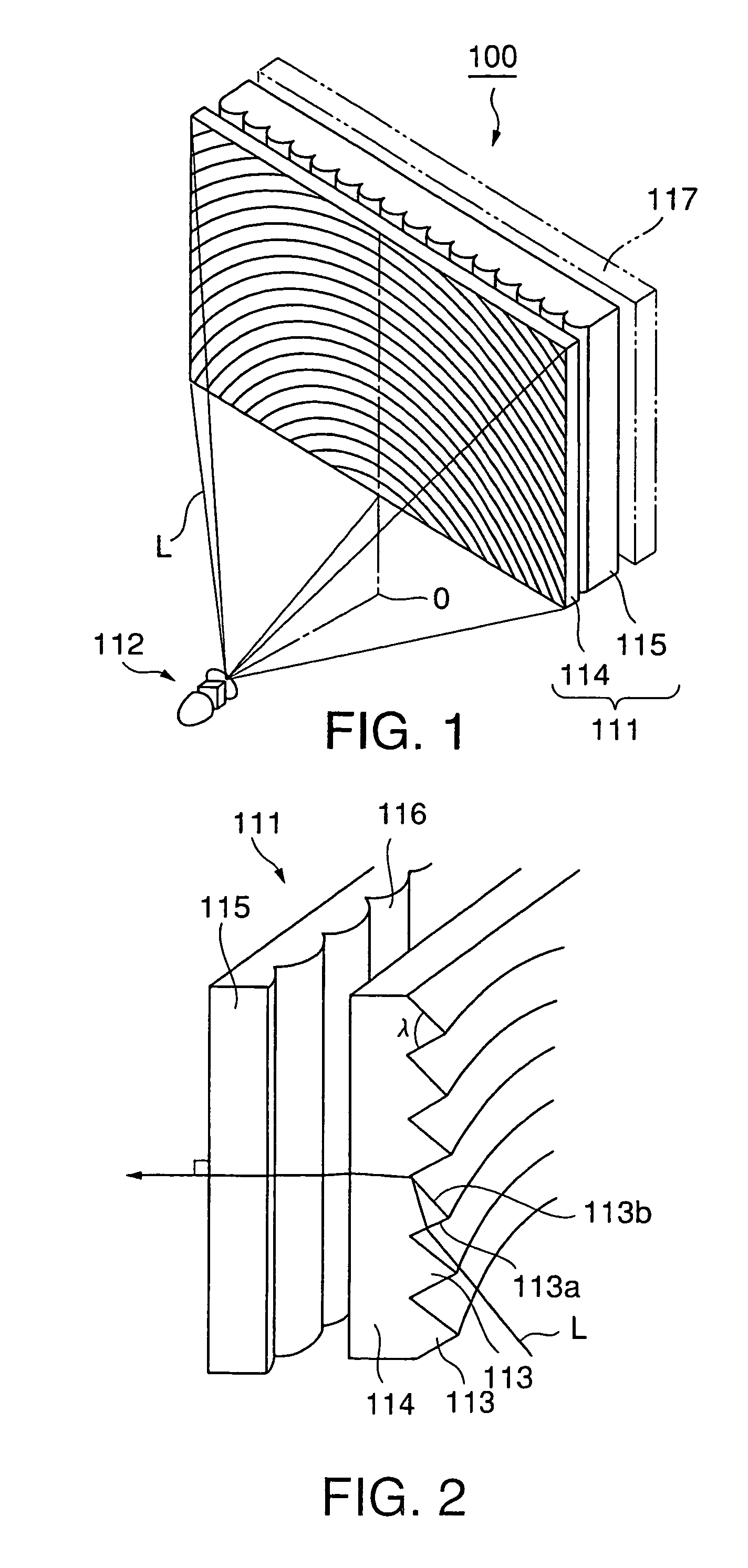
[0055]As shown in FIG. 1, a projection display 100 according to the first embodiment of the present invention comprises a projection screen 111 and a projection optical system 112 from which imaging light L is obliquely projected on the projection screen 111. The projection optical system 112 comprises an imaging light source composed of an LCD, DMD, or the like, and an optical system for spreading the imaging light emitted from the imaging light source.

[0056]The projection screen 111 is for letting imaging light L obliquely projected from the projection optical system 112 placed at its rear side emerge toward the viewer's side, and comprises a total reflection prism lens 114, and a lenticular lens 115 provided on the viewer's side of the total reflection prism lens 114.

[0057]Of these components, t...

first modification

(First Modification)

[0083]The above embodiment has been described with reference to the case where the apical angles λ of the unit prisms 113 are varied continuously over the entire screen plane. The present invention is not limited to this, and the apical angles λ of the unit prisms 113 may also be varied step-wise within the screen plane.

[0084]The first modification of the projection screen 111 shown in FIGS. 1 to 5 will be described with reference to FIGS. 6A, 6B, 7 and 8. Since the basic construction of this first modification is the same as that of the projection screen 111 shown in FIGS. 1 to 5, emphasis is, in the following description, laid on those points distinct from the projection screen 111 shown in FIGS. 1 to 5.

[0085]FIG. 6A is a view of a projection screen 111 according to the first modification, viewed from the incident side of the screen, and FIG. 6B is a view of the projection screen 111 according to the first modification (and a projection optical system 112), vie...

second modification

(Second Modification)

[0099]Next, the second modification of the projection screen 111 shown in FIGS. 1 to 5 will be described with reference to FIGS. 9A, 9B and 10. The second modification is a further modification of the above-described first modification, which can further ensure that the variation in the apical angle λ of each unit prism is not perceived. Since the basic construction of the second modification is the same as that of the first modification described above, emphasis is, in the following description, laid on those points distinct from the first modification.

[0100]FIG. 9A is a view of a projection screen 111 according to the second modification, viewed from the incident side of the screen, and FIG. 9B is a view of the projection screen 111 according to the second modification (and a projection optical system 112), viewed from the side of the screen.

[0101]As shown in FIGS. 9A and 9B, the projection screen 111 comprises a total reflection prism lens 114B having a plura...


PUM


Abstract

A projection screen 111 comprises a total reflection prism lens 114 and a lenticular lens 115 provided on the viewer's side of the total reflection prism lens 114. The total reflection prism lens 114 has a plurality of unit prisms 113 on its back surface (the outermost plane of incidence) on which imaging light L is incident. Each unit prism 113 has an apical angle λ that corresponds to the angle between the plane of incidence 113a and the plane of total reflection 113b, and the apical angles λ of the unit prisms 113 vary with the position of each unit prism 113 on the screen plane. In particular, the unit prisms 113 have apical angles λ varying continuously from 30° to 45° so that the apical angles λ on the side distant from the center O of the concentric circles are greater than the apical angles λ on the side close to this center O.

Description

FIELD OF THE INVENTION[0001]The present invention relates to a projection screen, especially a projection screen suitable for viewing imaging light that is obliquely projected on the screen from a cellular-structured imaging light source such as an LCD (Liquid Crystal Display) or DMD (Digital Micro-mirror Device), and to a projection display comprising the projection screen.BACKGROUND ART[0002]There has conventionally been known, as a display of rear projection type (rear projection type television), a projection display using three CRTs of red, green and blue colors as an imaging light source, in which imaging light emitted from such an imaging light source is projected on the back surface of a transmission projection screen to produce an image, which is viewed from the viewer's side.[0003]A projection screen for use in such a projection display is usually composed of a Fresnel lens sheet and a lenticular lens sheet, and allows imaging light emitted from an imaging light source to ...

Claims


Application Information

Patent Timeline
Patent Type & Authority Patents(United States)
IPC IPC(8): G03B21/56G02B3/08G03B21/62G02B5/02G02B5/04
CPCG02B3/005G03B21/625G02B5/045G03B21/62G02B5/04G02B5/02
Inventor GOTO, MASAHIROWATANABE, HITOMUYOSHIDA, YOSHIKISEKIGUCHI, HIROSHI
Owner DAI NIPPON PRINTING CO LTD
Why Eureka
Try Eureka