Structure of overhead lamp and mounting bracket for constructional vehicle

a technology for overhead lamps and mounting brackets, which is applied in the direction of fixed installation, transportation and packaging, and light and heating equipment, etc. it can solve the problems of affecting the normal performance affecting the angle of the fixing of the lamp apparatus, so as to achieve the effect of increasing the mounting angle of the lamp apparatus and securely fixing i

Inactive Publication Date: 2011-10-04
VISION MOTOR SPORTS
View PDF8 Cites 19 Cited by
  • Summary
  • Abstract
  • Description
  • Claims
  • Application Information

AI Technical Summary

Benefits of technology

[0025]Accordingly, the present invention has been made in view of the above problems, and it is an object of the present invention to provide a supporting structure for an overhead lamp for constructional vehicle, capable of increasing an illumination angle range by forming position controlling slits at lateral sides of a bracket, more securely fixing a main case of the lamp apparatus as position-controlled by supporting the main case through 4 points using a plurality of hinges and a plurality of the position controlling slits, and also securely fixing the main case to the bracket by connecting a connection screw that fixes a hinge bolt, restricting undesired rotation of the hinge bolt.
[0031]According to the lamp apparatus supporting structure for a vehicle as described above, the illumination angle of the lamp apparatus can be increased since the position controlling rib having the position controlling slit is extended to the rear side of the lateral sides of the side supporters and also provided at both sides of the fixing unit. Moreover, the main case is fixed to the fixing unit through a plurality of the position controlling slits that is, supported by 4 points, thereby being more securely fixed. Also, by fitting the connection screw with any one circumferential recess of the hinge bolt fastening lever, undesired separation of the hinge bolt and undesired change of the illumination angle of the main case can be prevented.

Problems solved by technology

On the other hand, although being expensive, the gas discharge bulb is even brighter than the halogen bulb since having a high luminous flux, and therefore is generally applied to high price cars.
However, it is disadvantageous to fix the lamp apparatus 6 to the roof panel 4 in an angle-uncontrollable state because the lamp apparatus 6 would illuminate different positions according to the working positions by the heavy equipment vehicle 2.
That is, when the lamp apparatus 6 is immovably fixed to the upper surface of the roof panel 4, the working areas can not be properly illuminated.
More specifically, while the heavy equipment vehicle 2 is moving to work in such a poor work environment, the position fixing lever 141 fixed merely by one position may be unfastened, thereby hindering the normal performance of the lamp apparatus.
As a result, unwanted change of the illumination angle of the lamp apparatus 6 may be caused.

Method used


Image

  • Structure of overhead lamp and mounting bracket for constructional vehicle
  • Structure of overhead lamp and mounting bracket for constructional vehicle
  • Structure of overhead lamp and mounting bracket for constructional vehicle

Examples


Embodiment Construction

[0038]Hereinafter, an exemplary embodiment of the present invention will be described in detail with reference to the accompanying drawings.

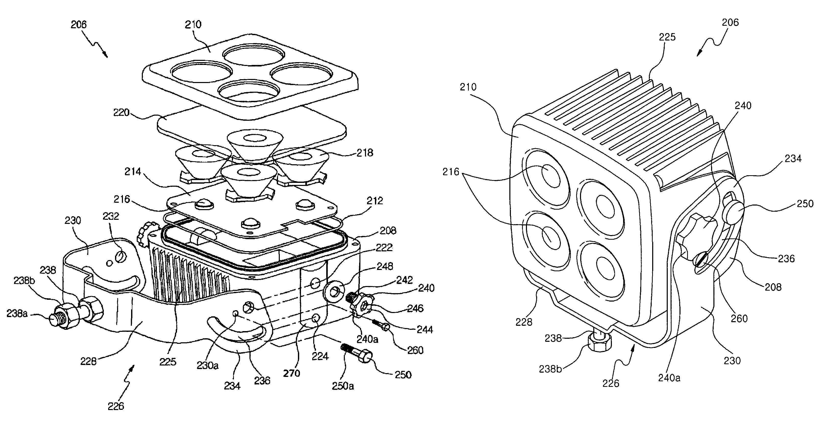
[0039]FIG. 4 is an exploded perspective view of an overhead lamp and supporting structure for constructional vehicle according to an embodiment of the present invention. FIG. 5 is a perspective view of the overhead lamp and supporting structure for constructional vehicle, according to the embodiment of the present invention. FIG. 6 is a side view of the lamp and supporting structure of FIG. 5.

[0040]Referring to the drawings, the overhead lamp structure according to the embodiment of the present invention, the position controlling slits are formed on lateral sides of a bracket so that the illumination angle range of the lamp apparatus can be increased. A main case of the lamp apparatus is supported by 4 points through pluralities of hinges and the position controlling slits. In addition, a fixing screw for fixing a hinge bolt not to be rotated is...


PUM


Abstract

A structure of overhead lamp and mounting bracket for constructional vehicle has developed to tilt the illuminating angle by controlling the position of slits at the lateral sides of bracket. The lamp is securely fixing at the controlled position at one of 4 positions and the position controlling slits. The main case is securely fixed to the bracket by installing a connection screw and a hinge bolt for restricting unwanted rotation of the hinge bolt. Accordingly, since a position controlling rib having a position controlling slit is extended rearward from side supporters, the illumination angle can be controlled within a greater range. The main case can be supported at 4 points through the plurality of position controlling slits. Furthermore, by fitting the connection screw with an outer circumferential recess of a hinge bolt fastening lever, rotational separation of the hinge bolt and change of the illumination angle of the main case can be prevented.

Description

BACKGROUND OF THE INVENTION[0001]1. Field of the Invention[0002]The present invention relates to the structure of overhead lamp and mounting bracket for constructional vehicle. More particularly, the overhead lamp with mounting bracket installed on a roof of the constructional vehicle has capable to control the illuminating direction by adjusting the tilt angle. A pair of arc-slits disposed at lateral surfaces of the mounting bracket has adopted for tiling and securely fixing the lamp at a controlled position.[0003]2. Description of the Related Art[0004]As generally known, a constructional vehicle has equipped with a pair of overhead lamps to secure the front views, while the vehicle is operating at night or in a dark place such as a tunnel. The overhead lamp has assembled with a lamp chamber consisted a main housing and a transparent cover, sub-housing consisted lens and reflecting mirror and mounted in the lamp chamber, and a head-lamp unit mounted in the sub-housing.[0005]The ove...

Claims


Application Information

Patent Timeline
Patent Type & Authority Patents(United States)
IPC IPC(8): F21S8/00
CPCB60Q1/0483B60Q1/00B60Q1/02
Inventor KO, IN-HONG
Owner VISION MOTOR SPORTS
Why Eureka
Try Eureka