Radar system

a radar and radar technology, applied in the field of radar systems, can solve the problems of requiring a large power source, requiring a large inventory of parts, and relying on physical components for their operation, so as to reduce the amount of phase noise, less phase noise, and the effect of reducing the number of times of multiplication

Active Publication Date: 2008-11-20
BLIGHTER SURVEILLANCE SYST LTD
View PDF15 Cites 16 Cited by
  • Summary
  • Abstract
  • Description
  • Claims
  • Application Information

AI Technical Summary

Benefits of technology

[0023]Conveniently the frequency generator further includes a fixed frequency oscillator such as a crystal oscillator or SAW (Surface Acoustic Wave) oscillator, which provides input to the first circuit portion. In one arrangement the tuning means of the first circuit portion preferably comprises a further frequency divider and a phase comparator, and the second circuit portion comprises a static frequency multiplier and a mixer which cooperate so as to reduce the frequency of signals that are input to the frequency divider of the second circuit portion. The further frequency divider associated with the first circuit portion is employed to step-down the fixed oscillator frequency, so as to control the frequency resolution of the signal generator. In relation to the second circuit portion, the frequency divider is employed to step-down the frequency of signals output from the mixer, and the output from the first and second frequency dividers are synchronised by a phase comparator, which generates said control signals (in ...

Problems solved by technology

A problem with the mechanical radar systems is that their operation is reliant on physical components and associated control and moving parts.
This inventory of parts is costly and can require a commensurately large power source.
Whilst radar systems incorporating such devices can provide an extremely accurate measure of the position of targets, a problem with these types of electronic devices is that adequate control of the beam requires often several arrays of electronics compon...

Method used


Image

  • Radar system
  • Radar system
  • Radar system

Examples


Embodiment Construction

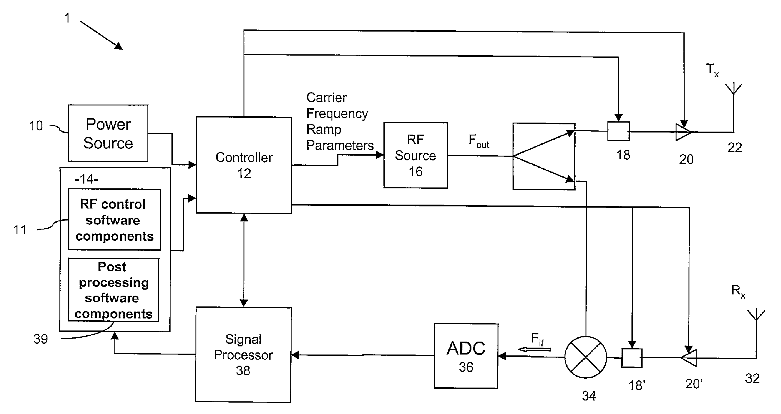
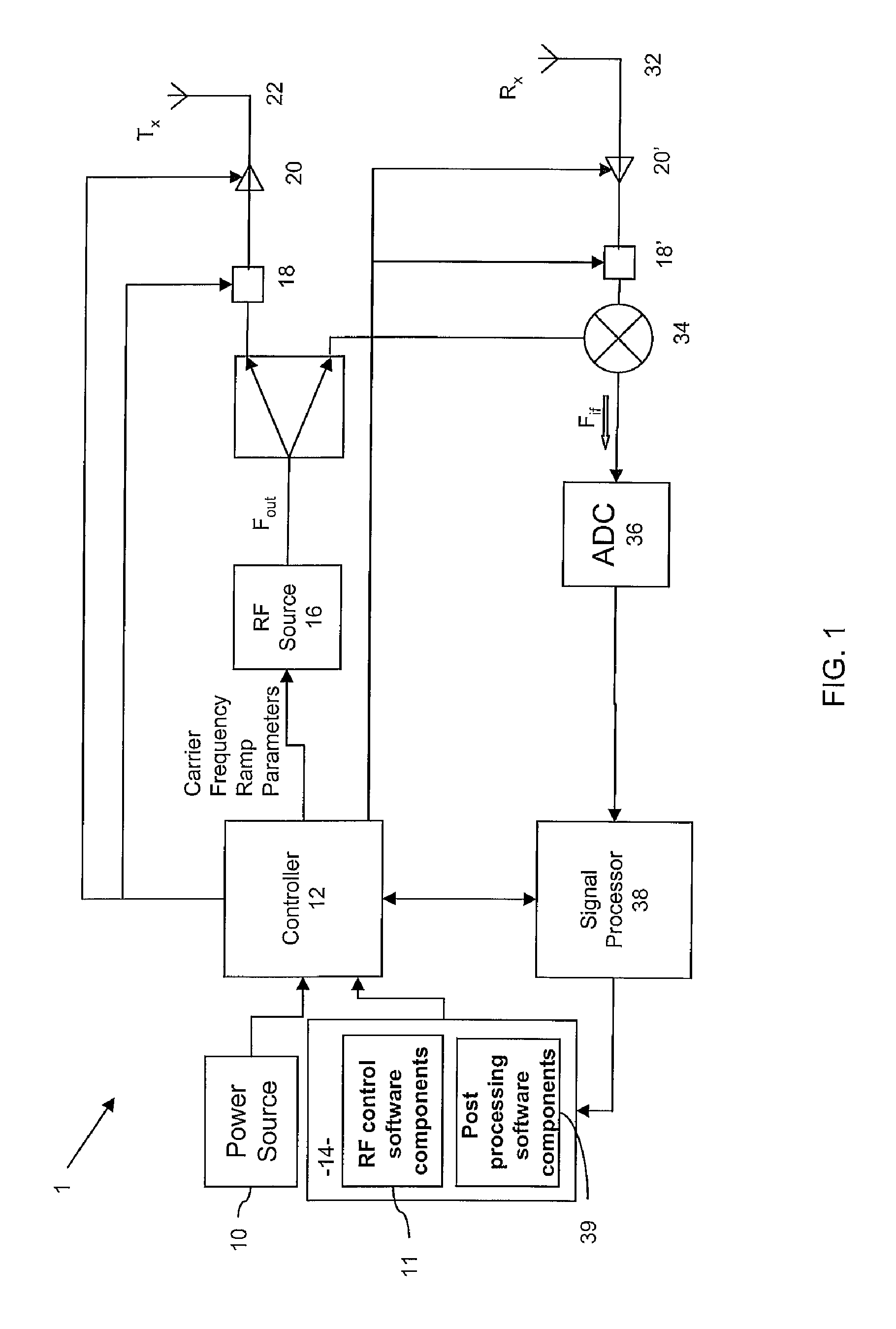
[0060]FIG. 1 shows a radar system 1 according to embodiments of the invention, comprising a power source 10, a controller 12, and a computer 14, the power source and computer 10, 14 being arranged to provide power to, and operational control over, the controller 12. The controller 12 comprises a microprocessor and a set of instructions (not shown) for execution thereby, effectively generating control signals that cause the RF frequency source, or signal generator 16, to output RF energy at a specified frequency FOUT, and this output signal, under control of switches 18 and amplifiers 20, drives antenna 22 (whilst the Figure shows a switch component 18, it will be appreciated that in this particular arrangement—in which there is only one antenna 22—the switch 18 is inessential). As will be described in more detail below, the RF frequency source 16 generates signals within a range of frequencies, causing the antenna 22 to transmit beams in different angular directions, thereby scannin...


PUM


Abstract

Embodiments of the invention are concerned with a radar system, and relates specifically to scanning radar systems that are suitable for detecting and monitoring ground-based targets.
In one aspect, the radar system is embodied as a scanning radar system comprising a frequency generator, a frequency scanning antenna, and a receiver arranged to process signals received from a target so as to identify a Doppler frequency associated with the target, wherein the frequency generator is arranged to generate a plurality of sets of signals, each set having a different characteristic frequency, the frequency generator comprising a digital synthesiser arranged to modulate a continuous wave signal of a given characteristic frequency by a sequence of modulation of patterns whereby to generate a said set of signals, and wherein the frequency scanning antenna is arranged to cooperate with the frequency generator so as to transceive radiation over a region having an angular extent dependent on the said generated frequencies.
Embodiments of the invention thus combine digital synthesiser techniques, which are capable of precise frequency generation and control, with passive frequency scanning and Doppler processing techniques. This enables accurate control of range and of scan rates, and enables optimisation of range cell size for factors such as slow and fast target detection and Signal to Noise ratio, and thus enables detection of targets located at distances considerably farther away than is possible with known systems having similar power requirements.

Description

CROSS REFERENCE TO RELATED APPLICATIONS[0001]This application claims the benefit of International Patent Application No. PCT / EP2006 / 068730 filed on Nov. 21, 2006 and entitled “RADAR SYSTEM”, the contents and teachings of which are hereby incorporated by reference in their entirety.FIELD OF THE INVENTION[0002]The present invention relates to a radar system, and relates specifically to scanning radar systems that are particularly, but not exclusively, suitable for detecting and monitoring ground-based targets.BACKGROUND OF THE INVENTION[0003]Radar systems are used to detect the presence of objects and to measure the location and movement of objects. In general, radar systems are designed for a specific application: to measure distance over a specified range of distances; over a specified scan region; within a specified level of accuracy; and in relation to a specified orientation. For radar systems that are required to scan over large distances, the antennas are required to generate p...

Claims


Application Information

Patent Timeline
IPC IPC(8): G01S13/00H01Q3/00
CPCG01S7/4008G01S13/227G01S13/24H01Q25/00G01S13/426H01Q3/22G01S13/343G01S13/42
Inventor PEARSON, GRAHAMGREENDALE, STEVESPREADBURY, DAVID
Owner BLIGHTER SURVEILLANCE SYST LTD
Why Eureka
Try Eureka