Microcutter stapling apparatus clamp and deploy mechanisms systems and methods

a micro-cutter and clamping technology, applied in the field of medical devices, can solve the problems of complex suturing procedures that are time-consuming and/or difficult to effectively perform, the suturing may be impractical or inability to be carried out in certain situations, and the suturing may be difficult to achieve in certain situations

Active Publication Date: 2014-06-26
AESCULAP AG
View PDF17 Cites 195 Cited by
  • Summary
  • Abstract
  • Description
  • Claims
  • Application Information

AI Technical Summary

Benefits of technology

[0013]Furthermore, the surgical stapling apparatus is configured to perform surgical treatments to a target tissue by operating a trigger member of the surgical stapling apparatus to activate a clamp gear combination, asserting a first trigger-force to drive a clamp spool member and a clamp slide member combination to place a stapling member in a first mode or trocar mode, asserting a second trigger-force to drive a clamp spool member and a clamp slide member combination to place the stapling member in a second mode or an open mode, asserting a third trigger-force to drive a clamp spool member and a clamp slide member combination to place the stapling memb...

Problems solved by technology

However, proper suturing requires significant skills to perform; in particular, complex suturing procedures can be time-consuming and/or very difficult to perform effectively.
Furthermore, suturing may be impractical or unfeasible in certain situations.
For example, suturing may be very difficult to perform in minimally-invasive surgical procedures where suturing tools may be required to be inserted through a small opening (often referred to as an access port) to gain access into a patient's body, and then the suturing operation is performed through the small access opening with extension tools to suture the target tissue.
In such minimally-invasive surgical procedures, the opening or access port...

Method used


Image

  • Microcutter stapling apparatus clamp and deploy mechanisms systems and methods
  • Microcutter stapling apparatus clamp and deploy mechanisms systems and methods
  • Microcutter stapling apparatus clamp and deploy mechanisms systems and methods

Examples


Embodiment Construction

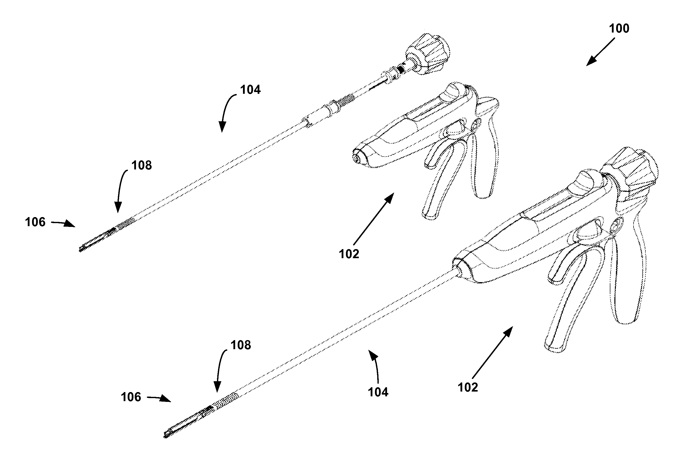
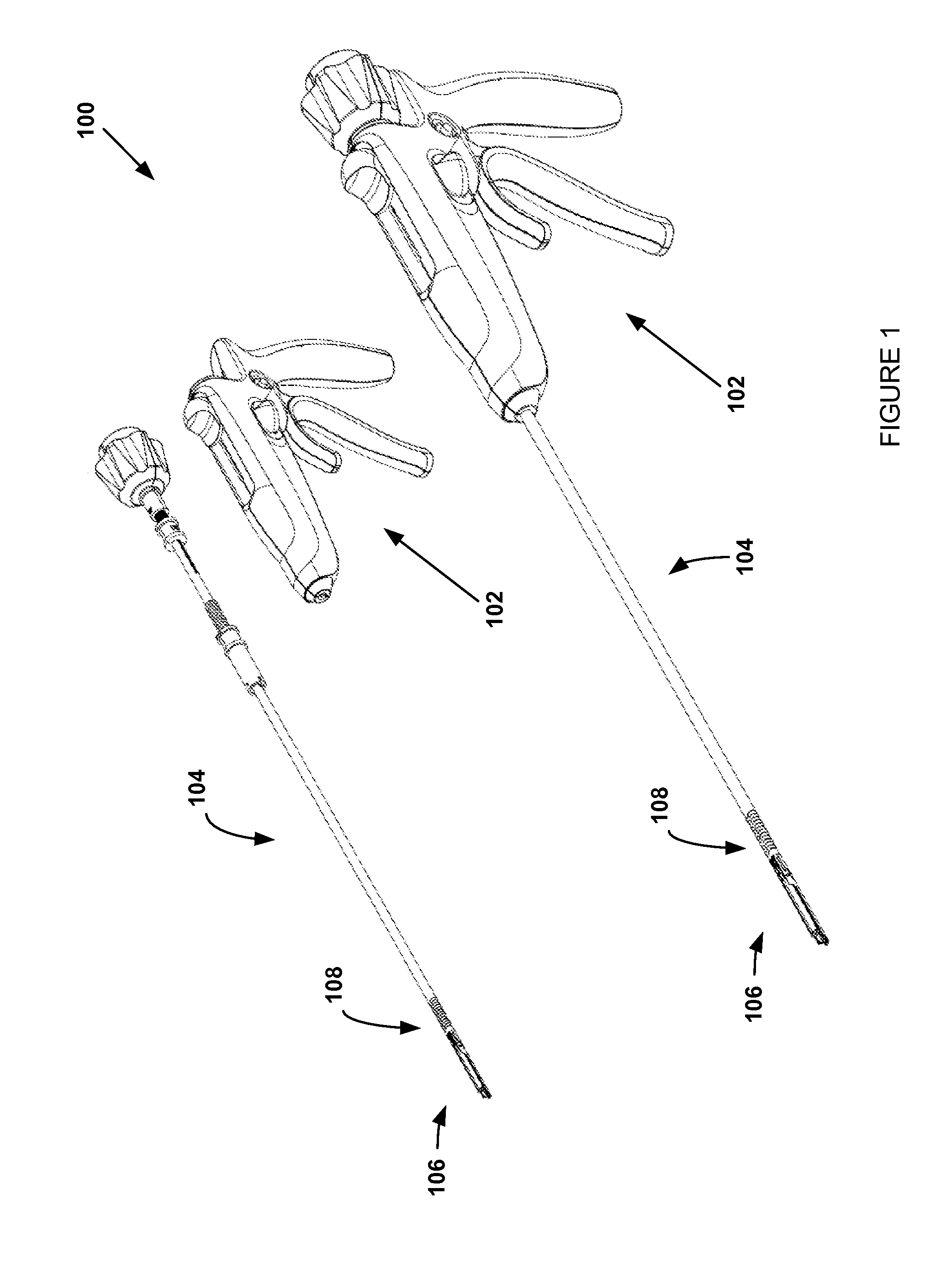
[0034]FIG. 1 illustrates examples of endo-cutter or micro-cutter and stapling systems 100 that can be alternatives or replacements to suturing. In particular, these endo-cutter or micro-cutter and stapling systems 100 are especially useful as alternatives or replacements to suturing in minimally-invasive surgical procedures. As illustrated in the figure, the operation of cutting and stapling is performed through a long slim shaft 104. The actual operations of clamping, cutting, and stapling of tissue are performed at the distal-end 106 of the shaft 104, and the control operations of these procedures are performed at the handle assembly 102. The distal-end 106 may include a stapling system comprising of a staple channel and a staple anvil, which are illustrated in FIG. 1. The staple channel may include a staple holder or a staple cartridge for holding staples. The staple anvil deforms the staples as they are deployed. As the staples are deployed, the staples pierce the target tissue ...


PUM

PropertyMeasurementUnit
Distanceaaaaaaaaaa

Abstract

A surgical stapling apparatus configured to perform stapling and/or cutting operations on a target tissue of a patient. The surgical stapling apparatus comprises of a mode selection switch to place the apparatus in either a clamping operational phase or a deployment operational phase. In the clamping operational phase, various clamp components are operated to facilitate loading of surgical staples into the stapling apparatus, if not preloaded, placement of the stapling apparatus to a target surgical site, and clamping of target tissue to be stapled and/or cut. In the deployment operational phase, various deployment components are operated to staple and/or cut the target tissue to one or more desired distance intervals to achieve the desired outcome for the surgical procedure.

Description

CROSS-REFERENCE TO RELATED APPLICATION[0001]This application is a non-provisional application of U.S. Provisional Application No. 61 / 745,426, Attorney Docket No. 358, filed on Dec. 21, 2012, which is incorporated herein by reference in its entirety.FIELD OF THE INVENTION[0002]The present invention relates generally to medical devices, and more particularly to endo-cutters or micro-cutters and stapling systems for performing various surgical procedures.BACKGROUND[0003]Traditionally, surgeons use sutures to close wounds and incisions, attach separate tissue structures to one another, and perform other medical or surgical functions during various surgical procedures or operations. However, proper suturing requires significant skills to perform; in particular, complex suturing procedures can be time-consuming and / or very difficult to perform effectively. Furthermore, suturing may be impractical or unfeasible in certain situations. For example, suturing may be very difficult to perform i...

Claims


Application Information

Patent Timeline
IPC IPC(8): A61B17/068
CPCA61B2017/2923A61B2017/00393A61B2017/00407A61B17/07207A61B2017/0046A61B17/068
Inventor KNODEL, BRYAN D.
Owner AESCULAP AG
Why Eureka
Try Eureka