Consolidated troffer

a technology of troffer and consolidated rod, which is applied in the field of led lighting system, can solve problems such as potential danger of electrical components

Active Publication Date: 2014-07-31
IDEAL IND LIGHTING LLC
View PDF11 Cites 24 Cited by
  • Summary
  • Abstract
  • Description
  • Claims
  • Application Information

AI Technical Summary

Problems solved by technology

With the use of LEDs comes the problem of how to disperse the concentrated light ray of the LED so as to create a more uniform and comfortable lighting environment.
Some of the more difficult regulatory restrictions to deal with involve the fact that the entire barrier between plenum space and occupied space must be bounded by an approved structural and fire rated material.
Furthermore, any potentially dangerous electrical components, including LED power sources must be isolated from any interaction with nearby materials or occupants.

Method used


Image

  • Consolidated troffer
  • Consolidated troffer
  • Consolidated troffer

Examples


Embodiment Construction

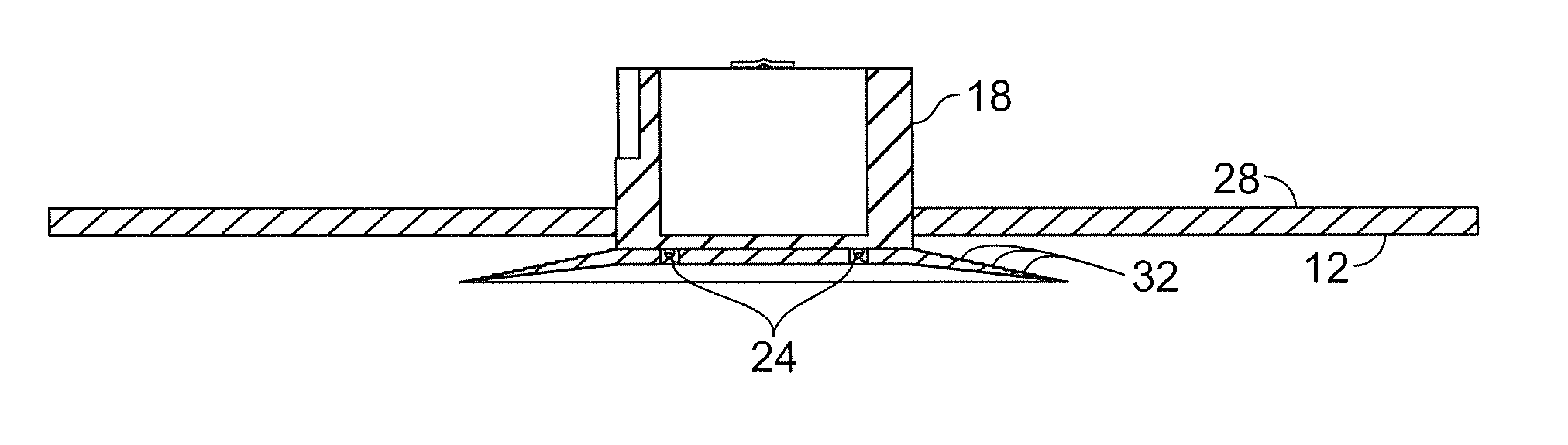
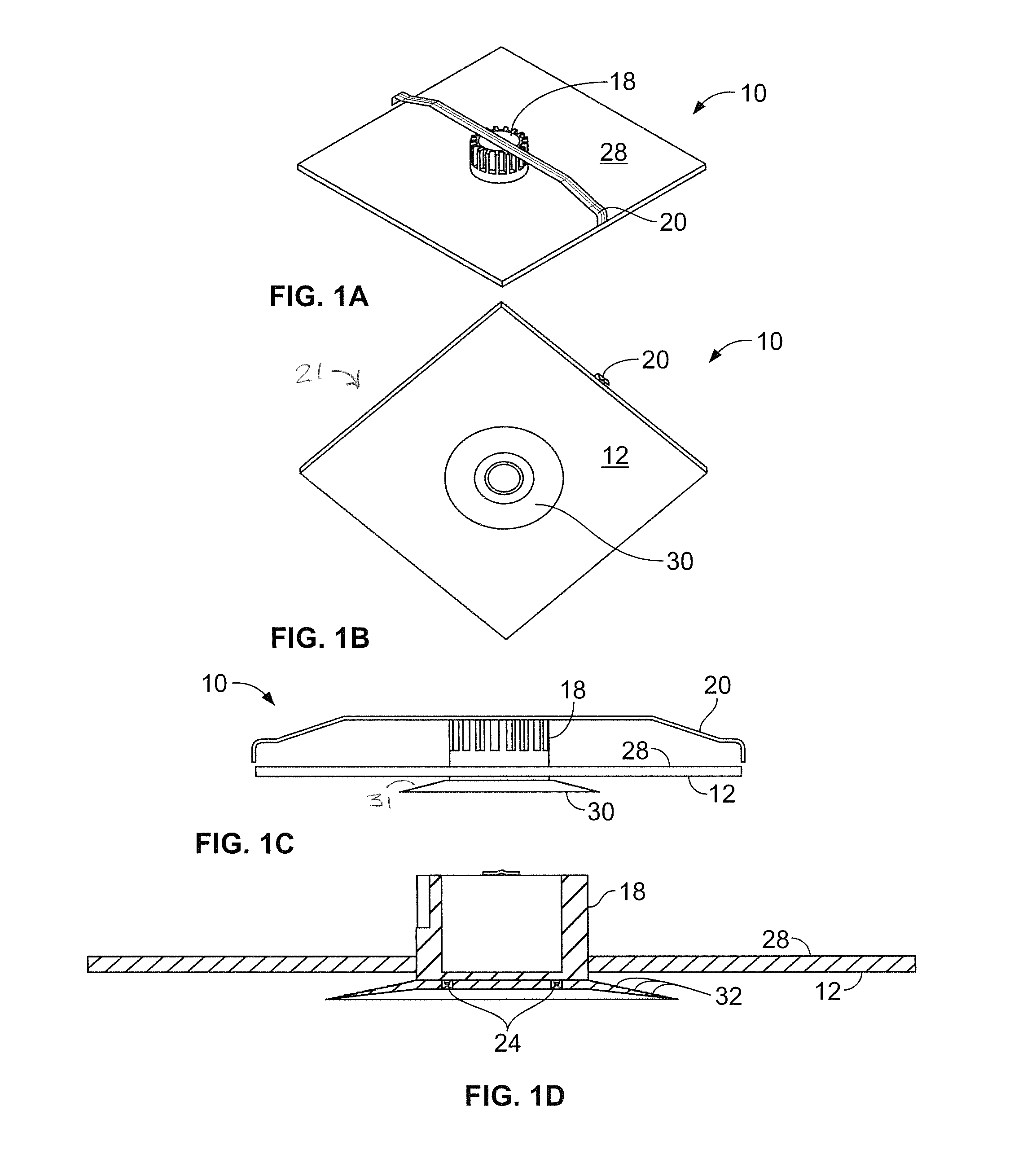
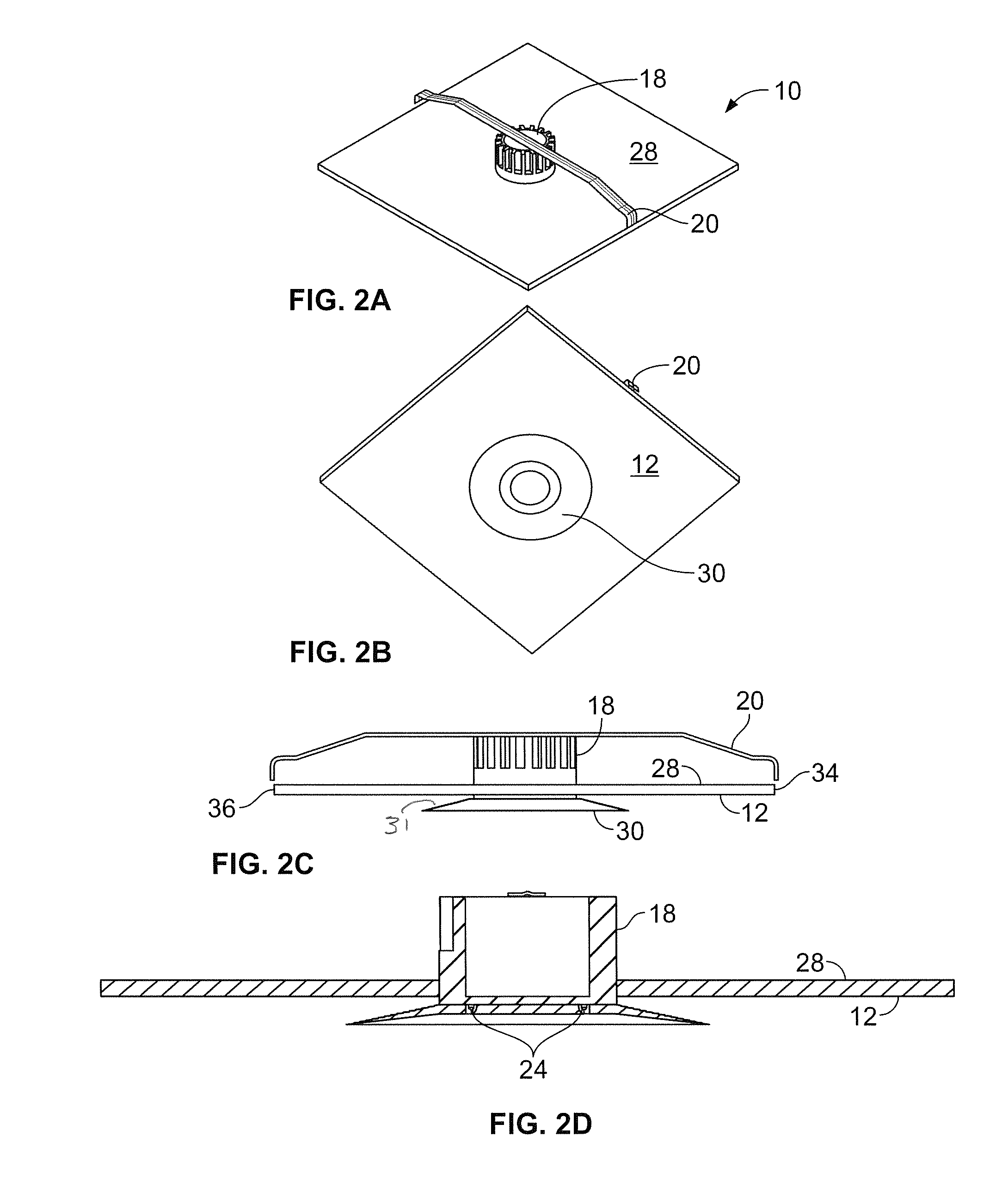
[0067]FIGS. 1-13E disclosed is a lighting system 10 comprised of a support element 21 having a reflective surface 12 and a luminaire 18 mounted on the support element 21. The luminaire 18 includes a light emitting diode (“LED”) light source 24 that provides light in a first pattern, and a redirection element 26 that receives the light from the LED light source 24 and redirects the light into a second pattern onto the reflective surface 12, wherein the reflective surface 12 occupies a first area, the LED light source 24 occupies a second area, and the first area is greater than the second area, as shown in FIGS. 13A-13E.

[0068]In an embodiment, when seen from below, the first area occupied by the reflective surface 12 is about 46 times greater than the second area occupied by the LED light source 24. In one particular version, the LED light source 24 occupies an area approximately 4 inches in diameter.

[0069]In still another embodiment, the LED light source 24 is positioned to direct i...


PUM


Abstract

A dropped-ceiling lighting system having a reflector positioned in an opening in a grid used to suspend a dropped ceiling, a lighting device including a light source mounted adjacent to the reflector, a structural support securing the lighting device to the grid, and a power source for the lighting device. Also discloses is a dropped-ceiling lighting system comprised of a reflector attached to a plenum barrier positioned in an opening in a grid used to suspend a dropped ceiling, a power source extends from a first edge of the plenum barrier to a second edge of the plenum barrier, and a light source is mounted to the power source.

Description

CROSS-REFERENCE TO RELATED PATENT APPLICATIONS[0001]This patent application claims the benefit of U.S. Provisional Patent Application Ser. No. 61 / 758,660, filed, Jan. 30, 2013, and is a continuation-in-part of U.S. patent application Ser. No. 13 / 839,949, filed, Mar. 15, 2013, U.S. patent application Ser. No. 13 / 840,563, filed, Mar. 15, 2013, U.S. patent application Ser. No. 13 / 841,074, filed, Mar. 15, 2013, U.S. patent application Ser. No. 13 / 842,521, filed, Mar. 15, 2013, U.S. patent application Ser. No. 13 / 841,651, filed, Mar. 15, 2013, and U.S. patent application Ser. No. 13 / 842,557, filed Mar. 15, 2013 and incorporates the disclosures of such applications by reference herein.FIELD OF THE INVENTION[0002]This invention pertains to a lighting system and, in particular, for a light emitting diode (LED) lighting system.BACKGROUND OF THE INVENTION[0003]Lighting systems have traditionally involved the use of incandescent or fluorescent lighting. Recent advances in the use of light emit...

Claims


Application Information

Patent Timeline
Patent Type & Authority Applications(United States)
IPC IPC(8): F21K99/00
CPCF21K9/52F21S8/04F21V7/0008F21Y2103/33F21Y2115/10G02B6/00G02B6/0021G02B6/0035G02B6/0038G02B6/0046
Inventor DURKEE, JOHN
Owner IDEAL IND LIGHTING LLC
Why Eureka
Try Eureka