Steering wheel squeeze-activated vehicle braking system

a technology of steering wheel and braking system, which is applied in the direction of brake action initiation, brake system, transportation and packaging, etc., can solve the problems of wasting precious time in an emergency, requiring a variable quantity of time for each of these motion activities, and being more intuitive, so as to achieve the effect of faster vehicle stop and faster vehicle stop

Active Publication Date: 2014-08-14
REDEVEX
View PDF15 Cites 29 Cited by
  • Summary
  • Abstract
  • Description
  • Claims
  • Application Information

AI Technical Summary

Benefits of technology

[0010]This invention resides in a brake-by-wire vehicle braking system augmented with “squeeze” sensors placed in the steering wheel of the vehicle. The system and method allow a vehicle operator to stop his or her vehicle more quickly in an emergency situation by eliminating the significant times that it takes to move a driver's foot from the accelerator to the brake pedal and then depress the brake pedal. An important objective is to achieve a faster vehicle stop by allowing the driver to optionally eliminate foot movement from the accelerator pedal to the brake pedal and also the depression of the brake pedal. This invention also potentially allows a driver to squeeze a steering wheel to slow a vehicle, perhaps to comply with a lower speed limit, or accomplish the fastest possible “hard-stop” in an emergency situation.

Problems solved by technology

Each of these motion activities requires a variable quantity of time.
Changes to how far the pedal can travel or to its resistance—if it feels harder or softer than normal—can be an indicator of problems such as low fluid levels or even a leak in the hydraulic system.
When ABS brakes are activated during heavy braking, the pulsations of the system can be felt by the driver through the pedal and this is normal, however, a pulsating feel during normal or light braking can also be an indicator of a potential braking system problem.
Such mechanisms are no more intuitive than moving one's foot onto a brake pedal, such that precious time may be wasted in an emergency.

Method used


Image

  • Steering wheel squeeze-activated vehicle braking system
  • Steering wheel squeeze-activated vehicle braking system
  • Steering wheel squeeze-activated vehicle braking system

Examples


Embodiment Construction

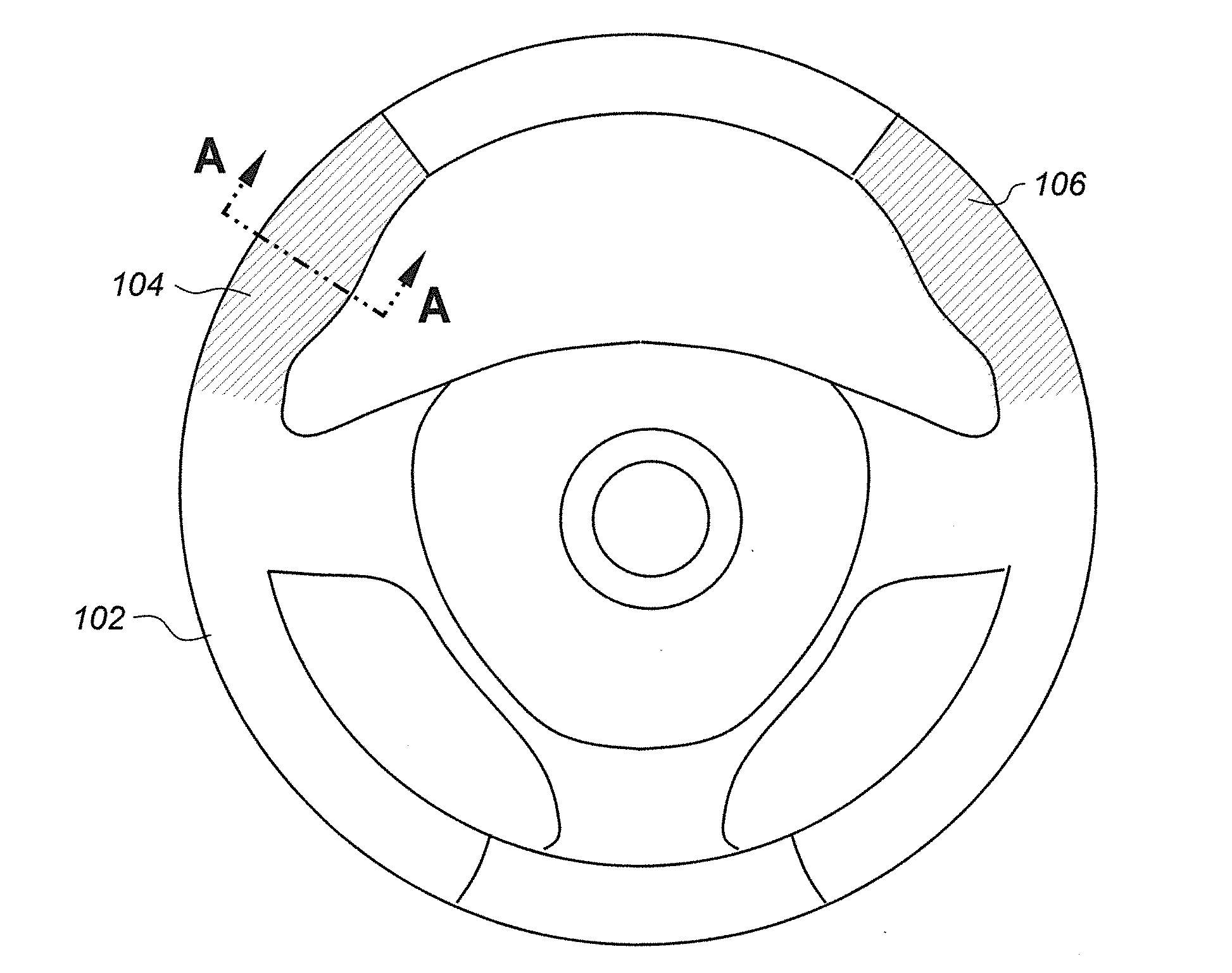
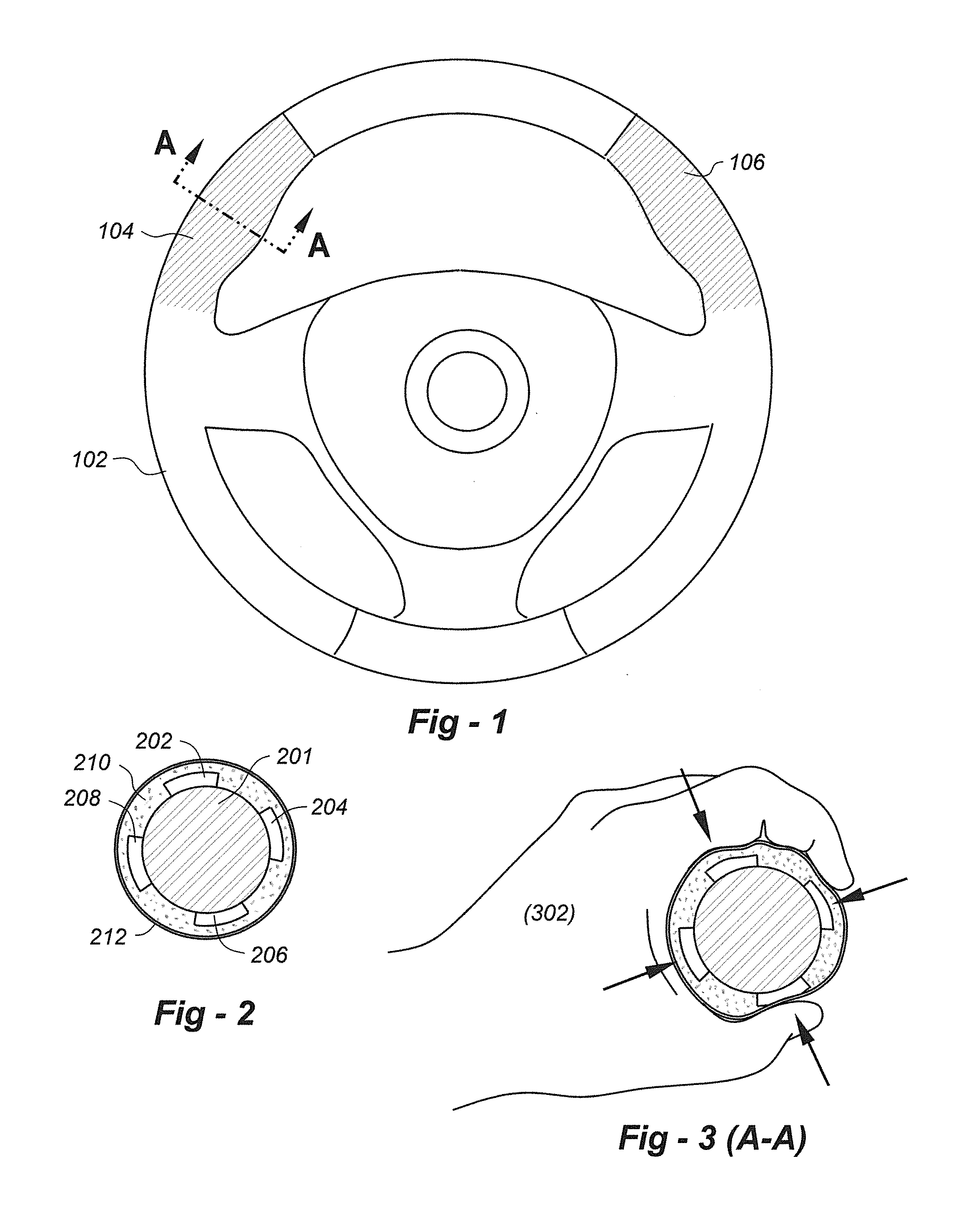
[0019]In accordance with this invention, the driver of a vehicle optionally “squeezes” the steering wheel to slow and / or to stop the vehicle. The driver does not in any way “push” or “pull” the steering wheel in any direction. FIG. 1 is a drawing that shows a steering wheel 102 with squeeze sensors placed in the “10 and 2” positions 104, 106 on the wheel. Although sensors are shown in these two positions it should be understood that other regions of the steering wheel may be instrumented, including the entire steering wheel.

[0020]In the preferred embodiment, multiple sensors are at least placed throughout the underside of the steering wheel (i.e., position 206 in FIG. 2) because the majority of experts no longer recommend grasping the wheel at the traditional “10” and “2” positions due to potentially serious damage to the driver's hand during inflation of the air bag located within the steering wheel. Indeed, auto manufacturers frequently include or exclude special grips, dividers o...


PUM


Abstract

A brake-by-wire vehicle braking system is augmented with “squeeze” sensors placed in the steering wheel of the vehicle enabling a vehicle operator to stop the vehicle more quickly in an emergency situation by eliminating the significant times that it takes to move a driver's foot from the accelerator to the brake pedal and then depress the brake pedal. An important objective is to achieve a faster vehicle stop by allowing the driver to optionally eliminate foot movement from the accelerator pedal to the brake pedal and also the depression of the brake pedal. This invention also potentially allows a driver to squeeze a steering wheel to slow a vehicle, perhaps to comply with a lower speed limit, or accomplish the fastest possible “hard-stop” in an emergency situation.

Description

FIELD OF THE INVENTION[0001]This invention relates generally to motor vehicle braking and, in particular, to a braking system operated by squeezing a vehicle's steering wheel.BACKGROUND OF THE INVENTION[0002]A vehicle traveling 60 miles per hour (MPH) moves 88 feet per second. In just one-tenth of a second at this speed, a vehicle travels 8.8 feet, which may be the difference between life and death in an accident event.[0003]Typically in a vehicle, there is no connection between the steering wheel or its column and the braking system, unless the vehicle has special equipment installed to accommodate a handicapped driver. Historically, there has been a physical linkage between a brake pedal and a car's master cylinder. The brake pedal works as a force multiplying lever and uses this leverage to transfer the effort from the driver's foot to the master cylinder. The more quickly the master cylinder receives a “brake” signal, the faster a vehicle can be brought to a stop. However, the v...

Claims


Application Information

Patent Timeline
Patent Type & Authority Applications(United States)
IPC IPC(8): B60T7/08B60T13/74
CPCB60T13/741B60T7/085B62D1/046B62D1/06
Inventor ROSENBAUM, RICHARD W.
Owner REDEVEX
Why Eureka
Try Eureka