
Shockproof centre wheel

a technology of centre wheel and shockproof technology, applied in the direction of frequency stabilisation mechanism, gearwork, instruments, etc., can solve the problems of watch no longer functioning, type of breakage, and use of hands with greater unbalance entail new problems, and achieve the effect of allowing some energy dissipation by friction

Active Publication Date: 2014-08-14
ETA SA MFG HORLOGERE SUISSE
View PDF8 Cites 7 Cited by
  • Summary
  • Abstract
  • Description
  • Claims
  • Application Information

AI Technical Summary

Benefits of technology

The invention allows for the absorption of shocks in a gear train by using an elastic element that allows for the elastic torsion of one component, namely the centre wheel. This torsion is achieved through a sliding motion between a centre arbour and a flange, which allows for some energy dissipation by friction. The elastic element also enables the modification of the amplitude and duration of the shock, making it lower in amplitude and longer in duration.

Problems solved by technology

The use of technologies permitting the use of hands with greater unbalance entails new problems:
In certain existing calibres, this type of breakage may occur in the event of a 5000 g shock, such as an accidental fall from the user's height.
Breakage means that the watch no longer functions, which strongly impacts the quality perceived by the user.
Indeed, if a counterweight can be added to the hands to reduce their unbalance and thereby reduce the torque exerted during a large shock, this type of solution impairs the appearance of the hands desired by the manufacturers.
The energy from a shock must be absorbed to permit the use of hands with significant unbalance, which are increasingly common with the current trend of increasing the diameter of watches.
CH Patent No 67295 in the name of BBC BROWN BOVERI & CIE discloses a wheel for heavy machinery including a toothed crown centred on a hub, with, just under the surface, a vibration or shock absorber device in the form of a tangentially mounted helical shock absorber spring, which is necessarily very bulky and unsuitable for horological applications.

Method used


Image

  • Shockproof centre wheel
  • Shockproof centre wheel
  • Shockproof centre wheel

Examples


second embodiment

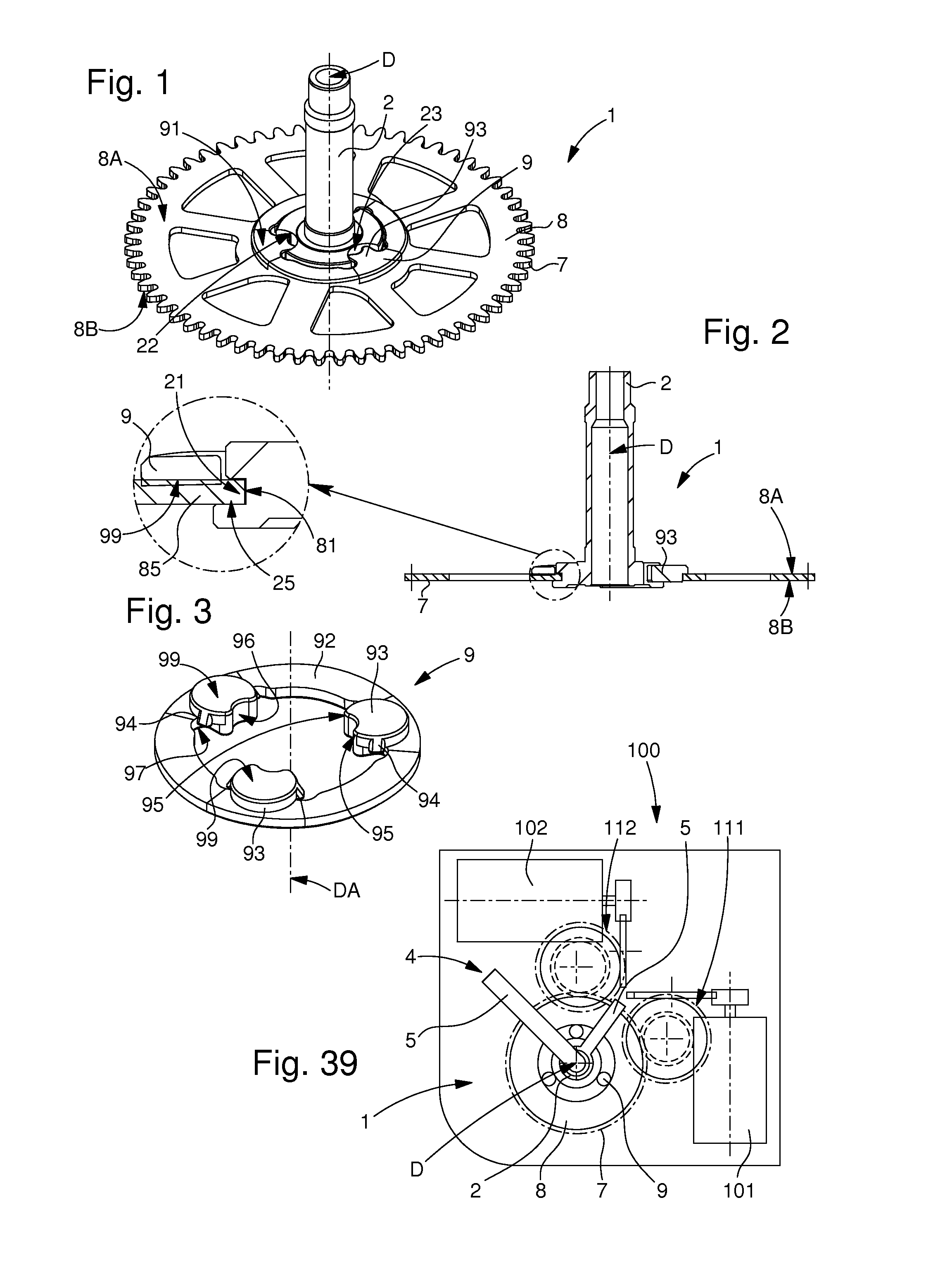
[0064]In the first and second embodiment, flexible elements 9 are substantially flat circular gaskets, and are wedged between flange 8 and arbour 2. Flange 8 pivots on arbour 2. A washer resting on and riveted to arbour 2 forms an axial stop member for flange 8. The gaskets transmit the torque between flange 8 and arbour 2. In the event of a shock, the gaskets are deformed and thus absorb part of the energy from the shock. When the shock has finished, flange 8 returns to its initial position relative to arbour 2.

[0065]In the particular case of the application of the invention to a centre wheel 1 carrying a hand 5, the shock is absorbed directly in centre wheel 1. That is to say, the energy from the shock, exerted by the hand unbalance is absorbed as soon as possible into the torque transmission chain.

[0066]This prevents the breakage of any gear trains and rotors made of plastic material and having small pivots, which may be contained in a movement 100. The advantages of these plasti...

first embodiment

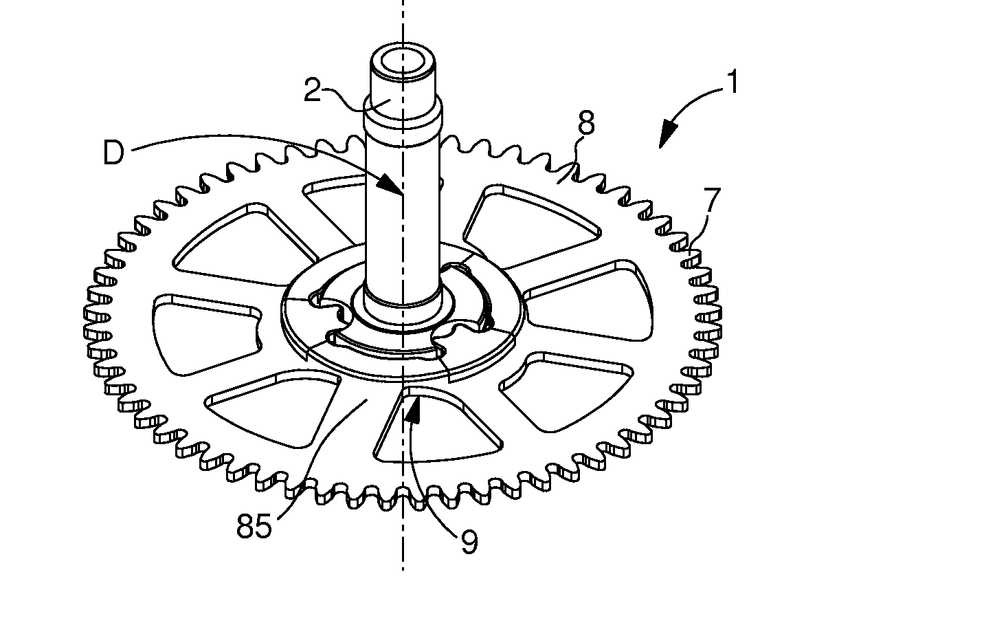
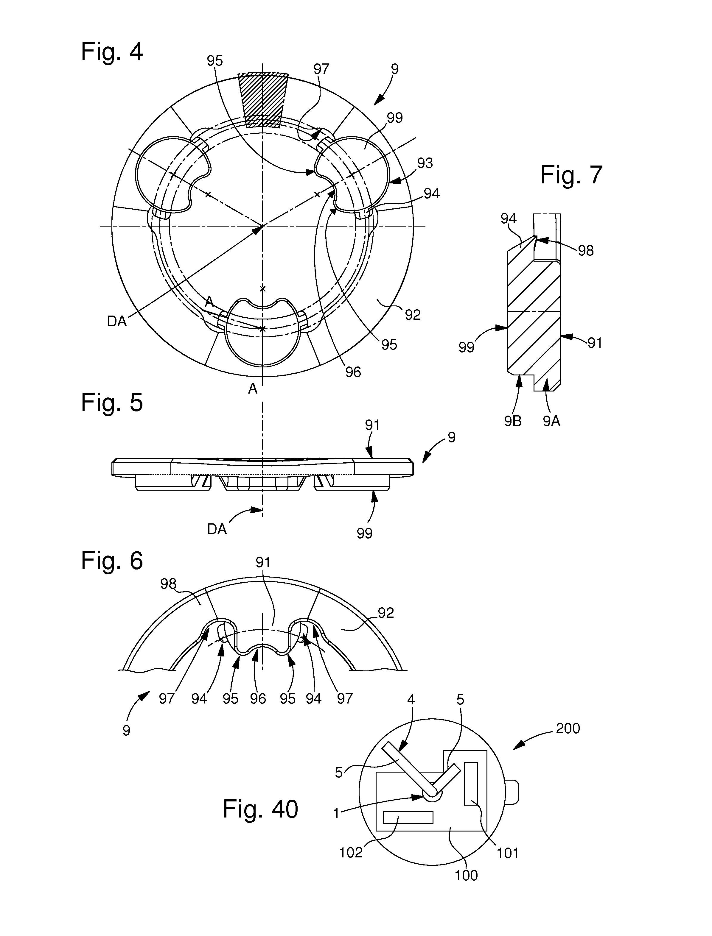
[0067]In the first embodiment illustrated in FIGS. 1 to 15, shockproof wheel 1, illustrated in the form of a minute wheel, includes a toothed flange 8 with a toothing 7 centred on an arbour 2, and secured to arbour 2 by a bayonet mechanism. This flange 8 is pivotally connected to arbour 2 by an elastomer or similar flexible element 9 that can deform in the event of a shock, said flexible element 9 is pressed onto a top surface 8A of flange 8, and snapped underneath a bottom surface 8B of flange 8.

[0068]This elastomer preferably has a hardness of between 50 and 70 Shore A, good results are obtained with a Shore hardness close to 65 Shore A. An “NBR”, or butadiene-acrylonitrile type copolymer is particularly suitable. Other elastomers having a similar hardness may also be suitable. Naturally, the choice of elastomer depends on the position of the wheel within the gear train, the level of unbalance of the wheel set(s) with which the wheel meshes and on the shock level to be absorbed. I...

third embodiment

[0096]In FIGS. 30 to 34, flexible element 9 is a substantially omega-shaped wire spring 6, held on the one hand in a front groove 28 of arbour 2, and on the other hand in a chamber 88 of flange 8, in which spring 6 is held substantially coplanar to flange 8. Shaped spring 6 is placed between flange 8 and arbour 2. Spring 6 cannot pivot on arbour 2. Branches 61 and 62 of the spring are pre-loaded on flange 8. A washer in abutment on and riveted to arbour 2 forms an axial stop member for flange 8 and confines and guides spring 6 in the plane of flange 8. In the event of a shock, branches 61 and 62 of spring 6 are deformed and thus absorb part of the energy from the shock. When the shock has finished, flange 8 returns to its initial position relative to arbour 2.


PUM


Abstract

Shockproof timepiece wheel for driving a component having non-zero unbalance relative to a pivot axis of this wheel, this wheel includes, on the one hand, an arbour for pivotally guiding the wheel about this pivot axis, and on the other hand, a drive means arranged or assembled on a flange of this wheel, this wheel including at least one flexible element between this arbour and this flange.This flange includes a cylindrical shoulder cooperating in abutment for centring purposes with a complementary cylindrical shoulder comprised in this arbour to ensure the perfect concentricity of this drive means (7) with this arbour.

Description

[0001]This application claims priority from European patent application No. 13154875.2 filed Feb. 12, 2013, the entire disclosure of which hereby incorporated by reference.FIELD OF THE INVENTION[0002]The invention concerns a shockproof timepiece wheel for driving a component having non-zero unbalance relative to a pivot axis of said wheel, said wheel includes, on the one hand an arbour for pivotally guiding the wheel about said pivot axis, and on the other hand, a drive means arranged or assembled on a flange of said wheel, said wheel including at least one flexible element between said arbour and said flange.[0003]The invention further concerns a timepiece movement including a wheel of this type carrying one said component having non-zero unbalance relative to a pivot axis of said wheel.[0004]The invention also concerns a watch including at least one timepiece movement of this type.[0005]The invention concerns the field of protection of watches against the effects of shocks, in par...

Claims


Application Information

Patent Timeline
Patent Type & Authority Applications(United States)
IPC IPC(8): G04B17/20
CPCG04B17/20G04B13/021G04B35/00G04B13/023G04B19/044
Inventor LAGORGETTE, PASCALBALMER, RAPHAEL
Owner ETA SA MFG HORLOGERE SUISSE
Learn More