Shockproof centre wheel
a technology of centre wheel and shockproof technology, applied in the direction of instruments, horology, gearwork, etc., can solve the problems of watch no longer functioning, type of breakage, and increased difficulty in adjusting the hand balance, so as to achieve the effect of allowing some energy dissipation by friction
- Summary
- Abstract
- Description
- Claims
- Application Information
AI Technical Summary
Benefits of technology
Problems solved by technology
Method used
Image
Examples
second embodiment
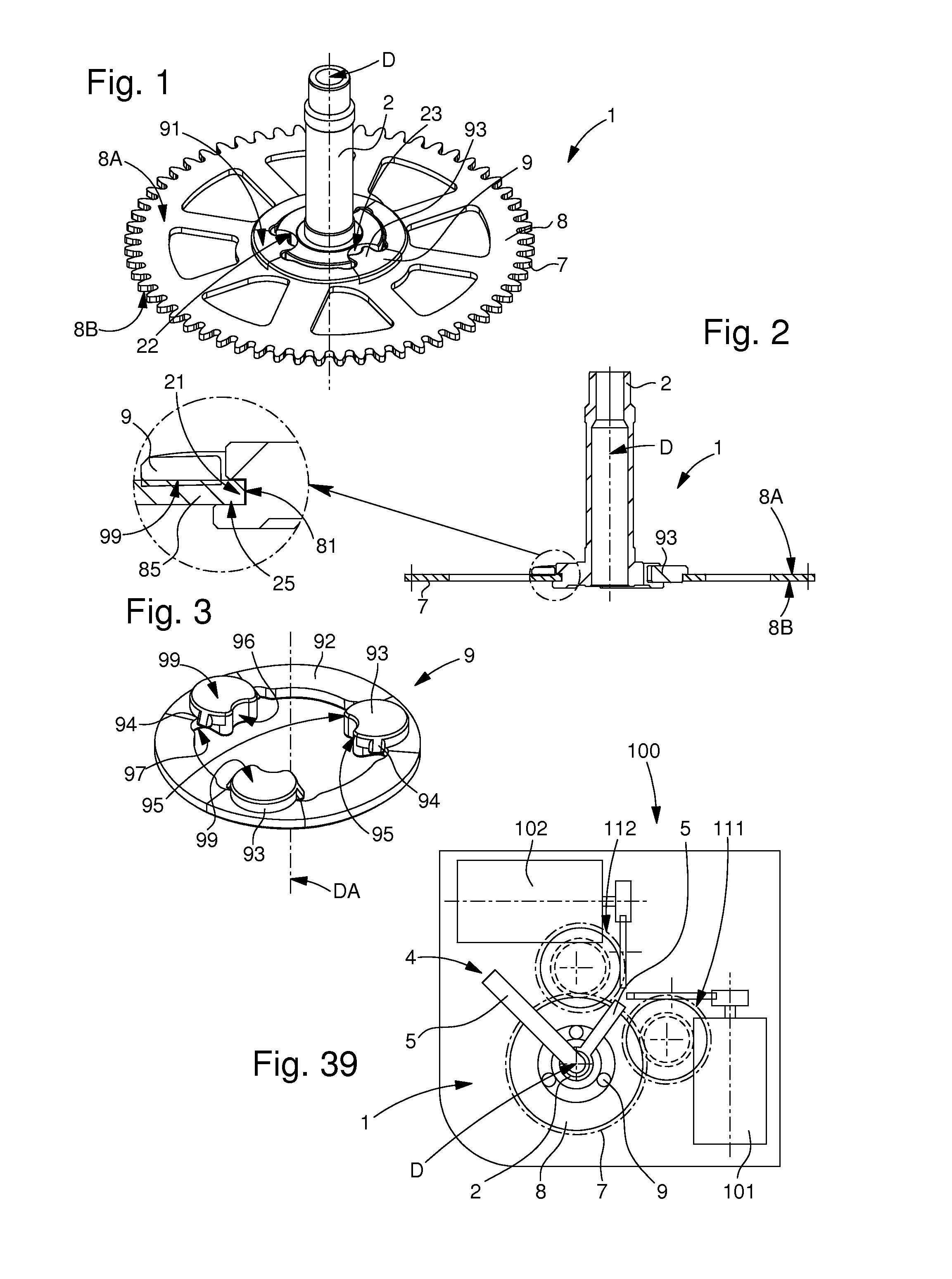
[0064]In the first and second embodiment, flexible elements 9 are substantially flat circular gaskets, and are wedged between flange 8 and arbour 2. Flange 8 pivots on arbour 2. A washer resting on and riveted to arbour 2 forms an axial stop member for flange 8. The gaskets transmit the torque between flange 8 and arbour 2. In the event of a shock, the gaskets are deformed and thus absorb part of the energy from the shock. When the shock has finished, flange 8 returns to its initial position relative to arbour 2.
[0065]In the particular case of the application of the invention to a centre wheel 1 carrying a hand 5, the shock is absorbed directly in centre wheel 1. That is to say, the energy from the shock, exerted by the hand unbalance is absorbed as soon as possible into the torque transmission chain.
[0066]This prevents the breakage of any gear trains and rotors made of plastic material and having small pivots, which may be contained in a movement 100. The advantages of these plasti...
first embodiment
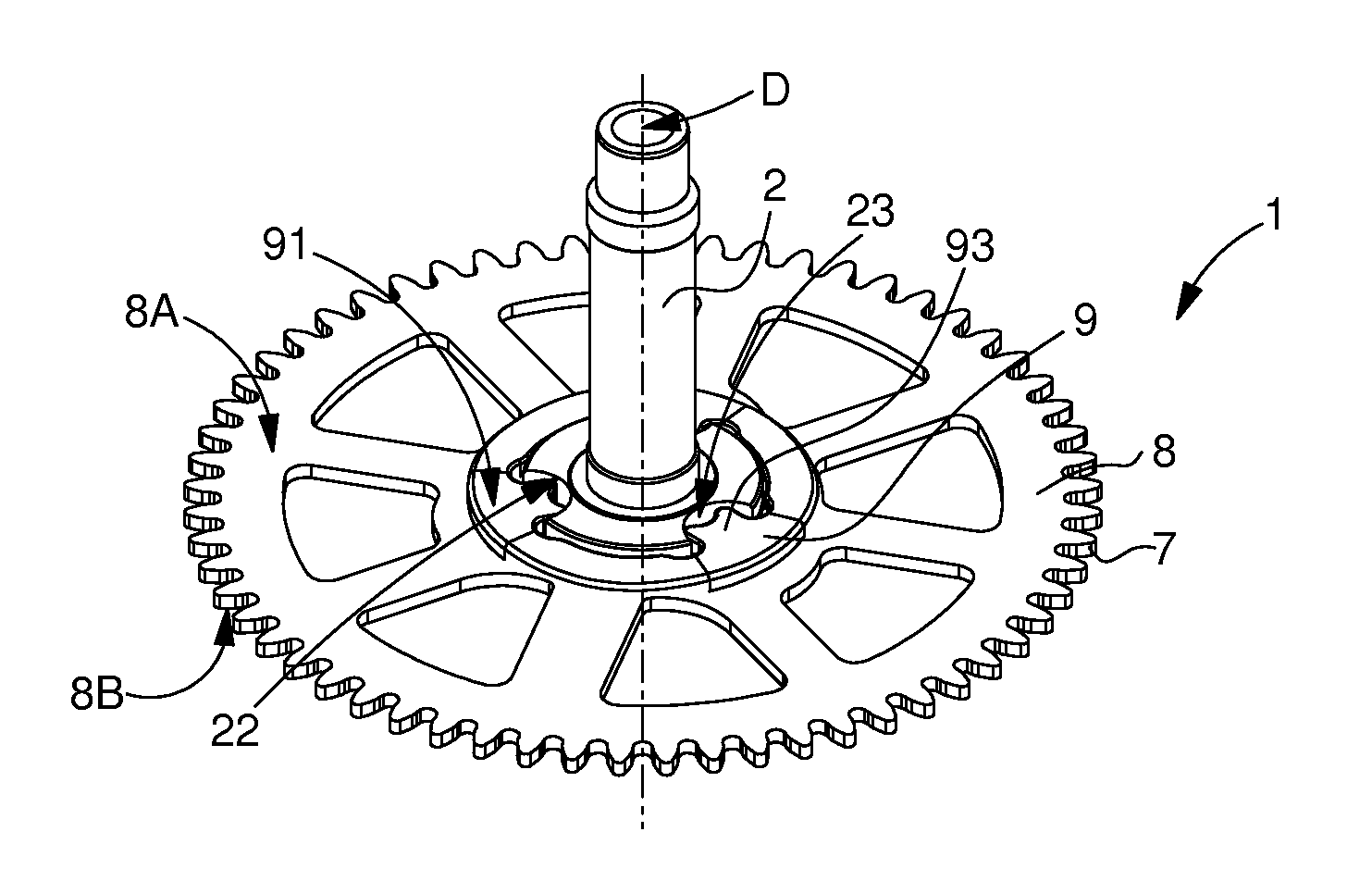
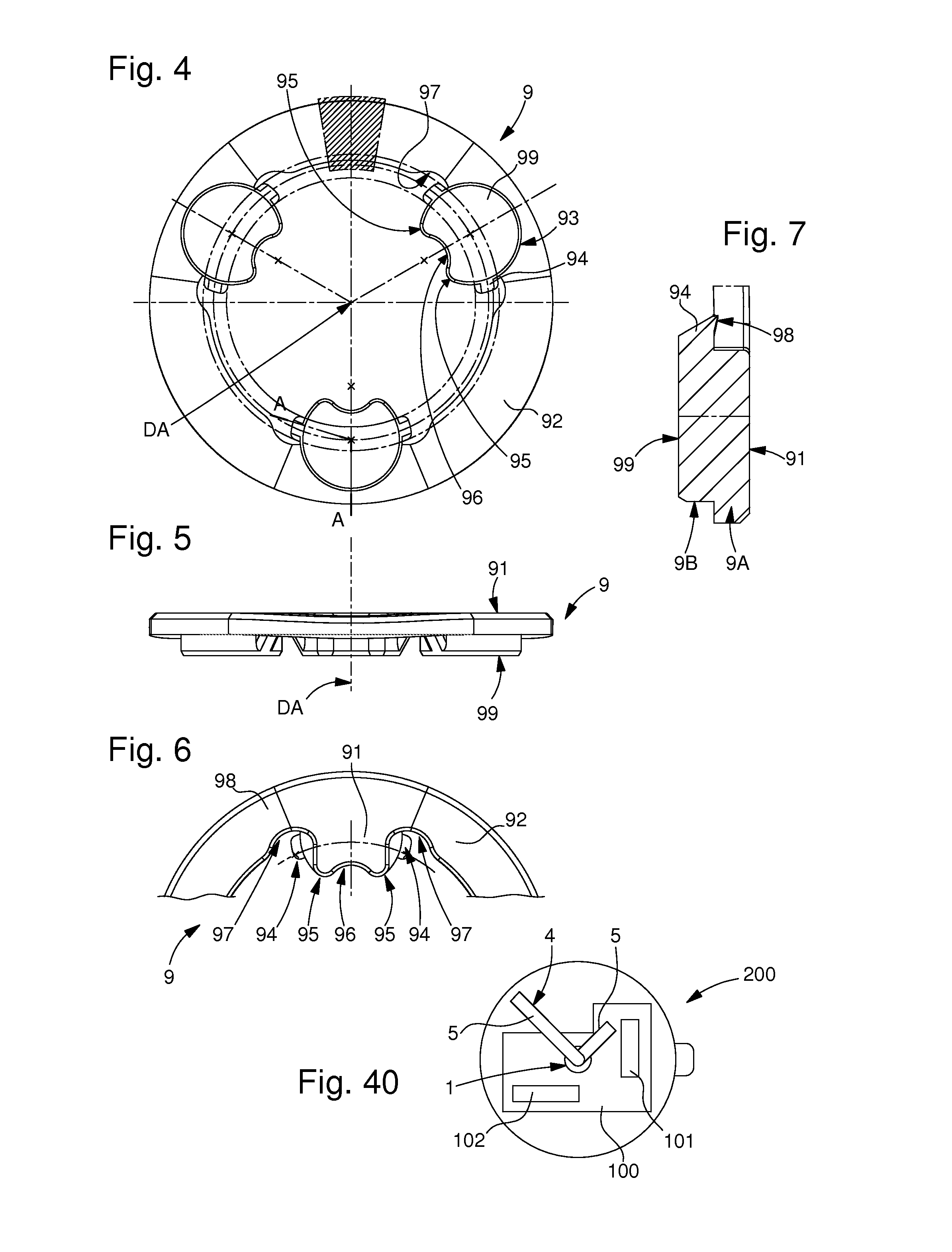
[0067]In the first embodiment illustrated in FIGS. 1 to 15, shockproof wheel 1, illustrated in the form of a minute wheel, includes a toothed flange 8 with a toothing 7 centred on an arbour 2, and secured to arbour 2 by a bayonet mechanism. This flange 8 is pivotally connected to arbour 2 by an elastomer or similar flexible element 9 that can deform in the event of a shock, said flexible element 9 is pressed onto a top surface 8A of flange 8, and snapped underneath a bottom surface 8B of flange 8.
[0068]This elastomer preferably has a hardness of between 50 and 70 Shore A, good results are obtained with a Shore hardness close to 65 Shore A. An “NBR”, or butadiene-acrylonitrile type copolymer is particularly suitable. Other elastomers having a similar hardness may also be suitable. Naturally, the choice of elastomer depends on the position of the wheel within the gear train, the level of unbalance of the wheel set(s) with which the wheel meshes and on the shock level to be absorbed. I...
third embodiment
[0096]In FIGS. 30 to 34, flexible element 9 is a substantially omega-shaped wire spring 6, held on the one hand in a front groove 28 of arbour 2, and on the other hand in a chamber 88 of flange 8, in which spring 6 is held substantially coplanar to flange 8. Shaped spring 6 is placed between flange 8 and arbour 2. Spring 6 cannot pivot on arbour 2. Branches 61 and 62 of the spring are pre-loaded on flange 8. A washer in abutment on and riveted to arbour 2 forms an axial stop member for flange 8 and confines and guides spring 6 in the plane of flange 8. In the event of a shock, branches 61 and 62 of spring 6 are deformed and thus absorb part of the energy from the shock. When the shock has finished, flange 8 returns to its initial position relative to arbour 2.
PUM
 Abstract
Description
Claims
Application Information
 - R&D
- Intellectual Property
- Life Sciences
- Materials
- Tech Scout
- Unparalleled Data Quality
- Higher Quality Content
- 60% Fewer Hallucinations
Browse by: Latest US Patents, China's latest patents, Technical Efficacy Thesaurus, Application Domain, Technology Topic, Popular Technical Reports.
© 2025 PatSnap. All rights reserved.Legal|Privacy policy|Modern Slavery Act Transparency Statement|Sitemap|About US| Contact US: help@patsnap.com


