Breathing tube holder

a technology for a holder and a stent is applied in the field of stents for stents, which can solve problems such as discomfort for patients, and achieve the effect of avoiding pressure sores and avoiding pressure sores

Inactive Publication Date: 2014-08-28
MES
View PDF4 Cites 12 Cited by
  • Summary
  • Abstract
  • Description
  • Claims
  • Application Information

AI Technical Summary

Benefits of technology

[0003]In accordance with one embodiment of the invention, a faceplate assembly is provided that includes a faceplate frame that mounts over a patient's mouth, and a bite block that mounts on the faceplate frame and that controls the position and orientation of the breathing tube in its passage through the mouth so as to pass into the patient's trachea. The faceplate frame has a centerline that extends horizontally and in a forward-rearward direction through the middle of the patient's mouth. The bite block guides the breathing tube to position it at one side of the centerline, so the tube is clamped between locations of the patient's lips that lie to one side of the centerline. To avoid pressure sores and provide relief from discomfort at the lip clamping locations, the tube is detached from the bite block, the faceplate assembly is turned 180°, and the tube is reattached to the bite block. This results in the tube being clamped between locations of the patient's lips that lie on the opposite side of the centerline. By occasionally moving the tube from one side of the mouth to the other side, applicant can avoid pressure sores on the patient's lips.
[0004]The breathing tube is mounted on the bite block by inserting it sideward into an open side of a tube guide of the bite block. Then an adhesive tape is wrapped around the tube and around the front of the bite block to fix them together. The adhesive tape can be easily removed, the faceplate frame turned 180°, and another piece of tape applied.

Problems solved by technology

After awhile, the patient may experience discomfort due to the same spot on his / her lips lying clamped against the tube.

Method used


Image

  • Breathing tube holder
  • Breathing tube holder
  • Breathing tube holder

Examples


Embodiment Construction

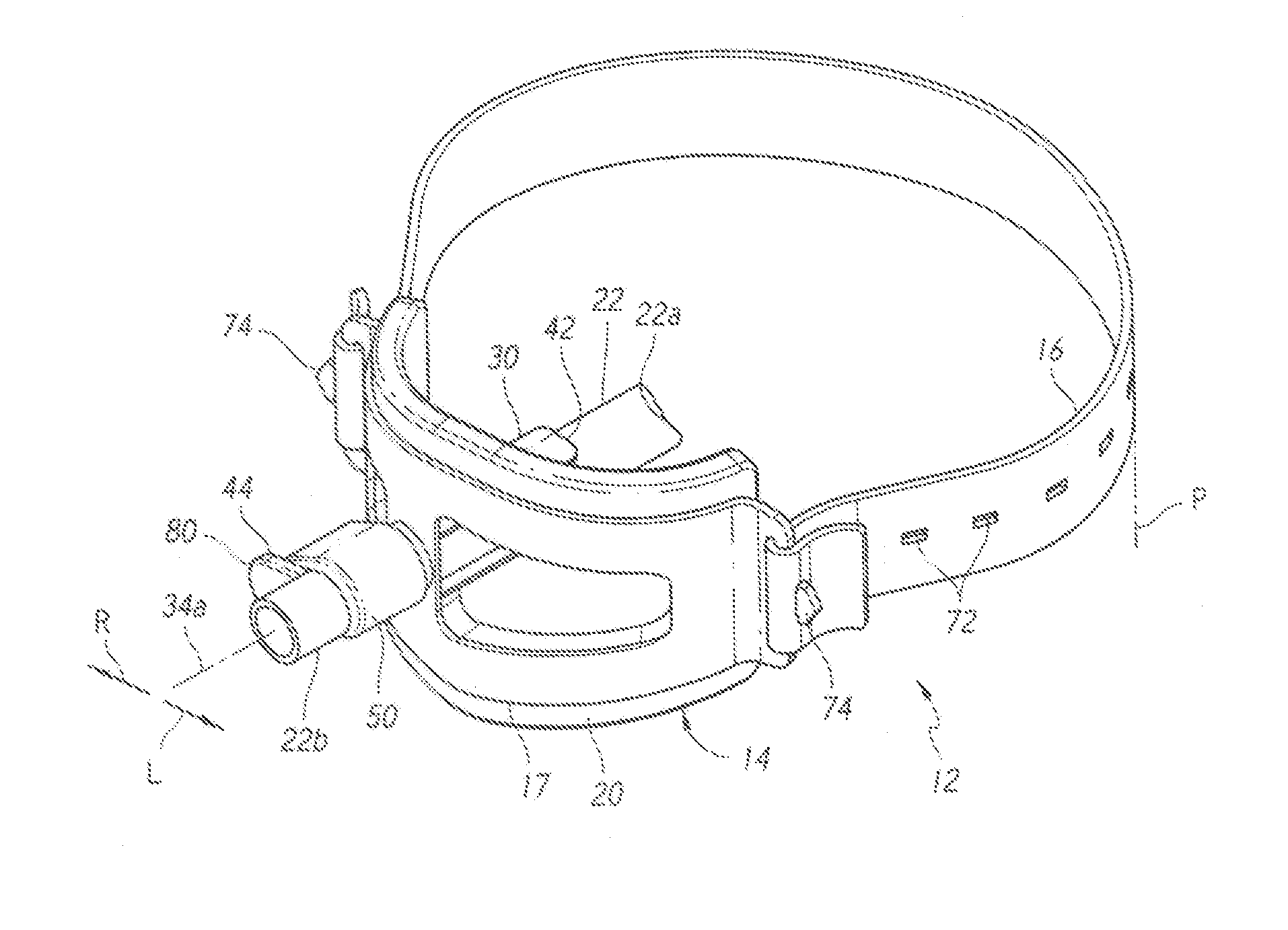
[0013]FIG. 1 shows a faceplate assembly 12 mounted on a patient P, and including a faceplate frame 14 mounted over the patient's face. An elastic band 16 holds the frame against the mouth region of the patient's face (the mouth region includes areas above and below the mouth). The faceplate frame includes a mask 17 of rigid material and a resilient foam backing 20 that actually contacts the patient's face. The figure also shows an endotracheal tube, or breathing tube 22 installed on the faceplate frame. The tube has a rear end 22A that extends to the patient's trachea and has an opposite front end 22B that extends to a source that repeatedly pumps air or other gas to the patient for breathing.

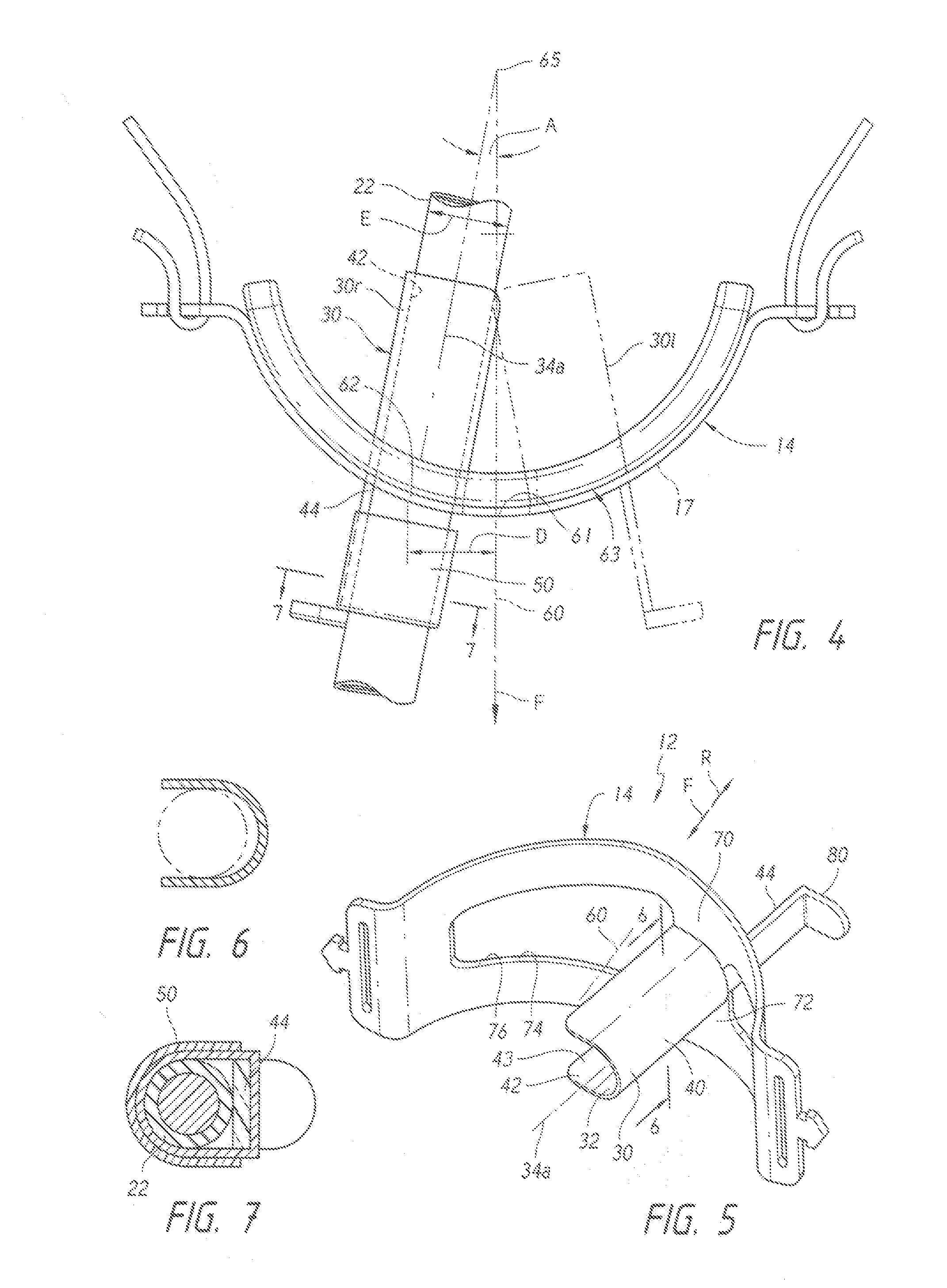
[0014]The faceplate assembly 12 (FIG. 5) includes a bite block 30 that has a passage 42 with a passage axis 34a that the breathing tube extends along. The bite block 30 has a rear tube guide part 40 that lies rearward of the middle of the faceplate frame 14 and that has an open side 43. The tub...


PUM


Abstract

A faceplate assembly that includes a faceplate frame (14) that mounts on a patient's face and a bite block (30) that holds an endotracheal tube (22) that extends into a patient's trachea to assist breathing. The tube is easily mounted on the bite block, and the tube can be shifted sidewardly to reduce discomfort to the lips of the patient. The bite block has a passage (42) through which the tube extends, the passage being spaced (D) sideward from the faceplate centerline (60). The faceplate can be removed from the patient, turned 180° about the centerline, and reinstalled using adhesive tape, to shift the bite block to the opposite side of the patient's mouth.

Description

CROSS-REFERENCE[0001]Applicant claims priority from U.S. provisional patent application Ser. No. 61 / 603,918 filed Feb. 27, 2012.BACKGROUND OF THE INVENTION[0002]Some patients with respiratory ailments who need breathing assistance, require that an endotracheal tube, or breathing tube, extend into their trachea to carry air to the lungs, as from a controlled air pump. The tube extends from outside the patient, through the mouth, and into the trachea. The patient wears a facemask assembly at a predetermined position on the face. After awhile, the patient may experience discomfort due to the same spot on his / her lips lying clamped against the tube. The discomfort can be stopped by occasionally moving the tube to one side and then to the other side, of the mouth so different locations of the lips press against the tube. The time and effort required to shift the tube should be as little as possible.SUMMARY OF THE INVENTION[0003]In accordance with one embodiment of the invention, a facepl...

Claims


Application Information

Patent Timeline
Patent Type & Authority Applications(United States)
IPC IPC(8): A61M16/04
CPCA61M16/0497A61M16/0493
Inventor BORRE, MICHAEL KEVINBORRE, JAMES PATRICK
Owner MES
Why Eureka
Try Eureka