System and method for calibration of machine vision cameras along at least three discrete planes

a technology of machine vision and discrete object planes, applied in the field of system and method for calibrating vision system cameras with respect to a plurality of discrete object planes, can solve the problem of time-consuming and time-consuming calibration procedures, and achieve the effect of simplifying the calibration setup for the user and speeding up the calibration process

Active Publication Date: 2014-08-28
COGNEX CORP
View PDF6 Cites 33 Cited by
  • Summary
  • Abstract
  • Description
  • Claims
  • Application Information

AI Technical Summary

Benefits of technology

[0010]This invention overcomes disadvantages of the prior art by providing a system and method for generating camera calibrations for a vision system camera along three or more (i.e. at least three) discrete planes in a 3D volume space that uses at least two (illustratively parallel) object planes at different known heights. For any third specified plane (illustratively parallel to one or more of the fisrt two planes at a specified height), the system and method then automatically generates accurate calibration data for the camera by a linear interpolation / extrapolation from the first two calibrations. Such technique is accurate in theory, and is free of the use of any explicit approximation. This alleviates the need to set the calibration plate or similar calibration object at more than two heights, speeding the calibration process and simplifying calibration setup for the user. Moreover, the illustrative system and method desirably enables calibration to heights typically not accessible by a calibration object (e.g. due to space constraints—such as an inside groove of a housing being imaged). The calibration plate can be calibrated at each height using a full 2D hand-eye calibration, or using a hand-eye calibration at the first height and then moving it to a second height with exclusive translation along the height (Z) direction (typically translation that is free of rotation about the Z axis as well as any translation or rotation with respect to the X and Y axes).

Problems solved by technology

Calibration is a procedure that is often time consuming and must occur within the space constraints of the work area.

Method used


Image

  • System and method for calibration of machine vision cameras along at least three discrete planes
  • System and method for calibration of machine vision cameras along at least three discrete planes
  • System and method for calibration of machine vision cameras along at least three discrete planes

Examples


Embodiment Construction

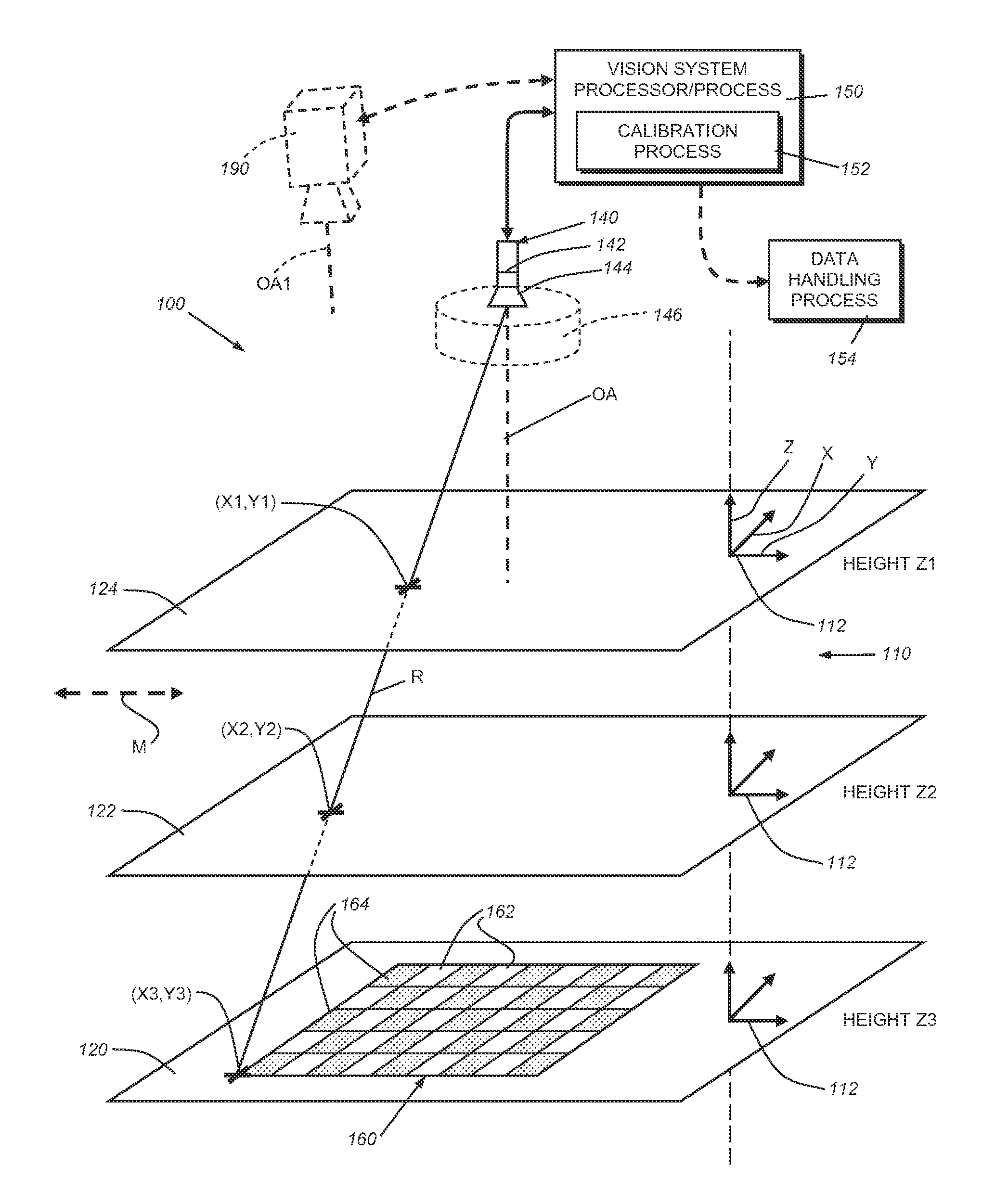
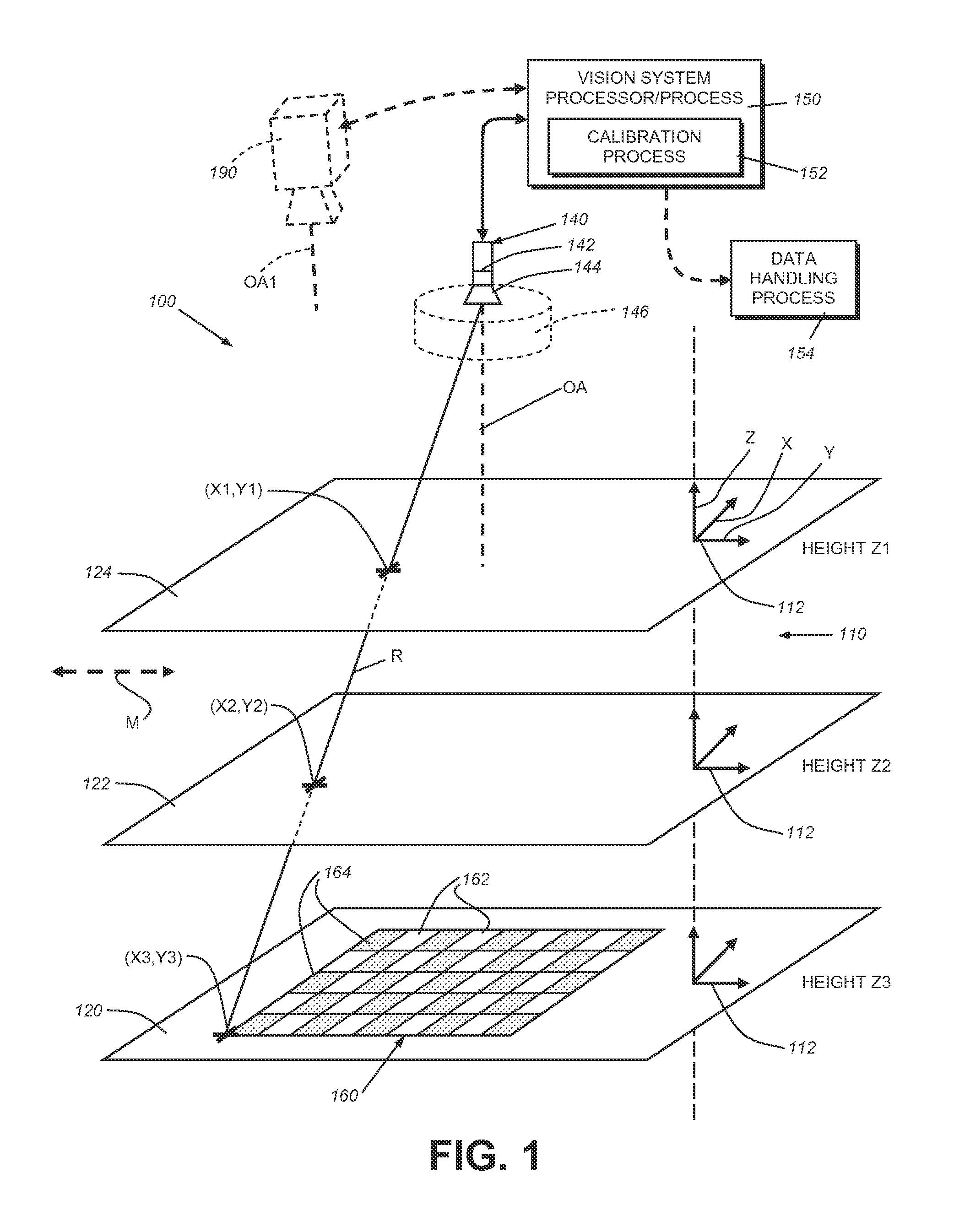
[0018]FIG. 1 shows a schematic diagram of a vision system camera arrangement 100 that acquires images of a scene 110 within three dimensions as indicated by the depicted motion coordinate (X, Y and Z) axes 112. The scene 110 entails three or more (at least three) discrete elevations as depicted by planes 120, 122 and 124. For the purposes of illustration, each of the planes 120, 122 and 124 is parallel, in that only the Z-axis elevation or “height” varies and there is no rotation about either the corresponding X or Y axis. Accordingly, the scene can be defined as a 2.5-dimensional (2.5D) space. That is, there exists variation in the location of an object along the Z-axis, but within defined planes (120, 122, 124, etc.) that remain parallel to each other. In further embodiments, and as described below, the planes can be non-parallel and separated along a more generalized axis of separation at some location passing through each plane. This axis of separation in the illustrative exampl...


PUM


Abstract

This invention provides a system and method for generating camera calibrations for a vision system camera along three discrete planes in a 3D volume space that uses at least two (e.g. parallel) object planes at different known heights. For any third (e.g. parallel) plane of a specified height, the system and method then automatically generates calibration data for the camera by interpolating / extrapolating from the first two calibrations. This alleviates the need to set the calibration object at more than two heights, speeding the calibration process and simplifying the user's calibration setup, and also allowing interpolation / extrapolation to heights that are space-constrained, and not readily accessible by a calibration object. The calibration plate can be calibrated at each height using a full 2D hand-eye calibration, or using a hand-eye calibration at the first height and then at a second height with translation to a known position along the height (e.g. Z) direction.

Description

FIELD OF THE INVENTION[0001]This invention relates to calibration of vision system cameras, and more particularly to systems and methods for calibrating vision system cameras with respect to a plurality of discrete object planes.BACKGROUND OF THE INVENTION[0002]In machine vision systems (also termed herein “vision systems”), one or more cameras are used to perform vision system process on an object or surface within an imaged scene. These processes can include inspection, decoding of symbology, alignment and a variety of other automated tasks. More particularly, a vision system can be used to inspect a flat work piece passing through an imaged scene. The scene is typically imaged by one or more vision system cameras that can include internal or external vision system processors that operate associated vision system processes to generate results. It is generally desirable to calibrate one or more cameras to enable it / them to perform the vision task(s) with sufficient accuracy and rel...

Claims


Application Information

Patent Timeline
Patent Type & Authority Applications(United States)
IPC IPC(8): H04N17/00
CPCH04N17/002G06T7/0018G06T7/80H04N23/00H04N23/60H04N23/62H04N23/683
Inventor LIU, GANGSHIVARAM, GURUPRASADMARRION, JR., CYRIL C.
Owner COGNEX CORP
Why Eureka
Try Eureka