Time of flight sensor

Active Publication Date: 2020-03-26
PHOTONIC VISION LTD
View PDF0 Cites 2 Cited by
  • Summary
  • Abstract
  • Description
  • Claims
  • Application Information

AI Technical Summary

Benefits of technology

[0050]The time of flight sensor may be a charge coupled device. The use of a charge coupled device allows for a very high fill factor, i.e. a very large percentag

Problems solved by technology

Sensors based on triangulation measurement techniques using structured illumination patterns have proven to be very successful in short range applications such as gesture control, gaming and industrial metrology but their inability to cope with high ambient light levels have tended to restrict their use to indoor applications or applications where the overall illumination level can be controlled.
Whilst such sensors can provide high resolution their performance is limited by random noise sources including intrinsic circuit noise and particularly the shot noise generated by ambient light.
This fill factor limitation reduces the sensitivity of the sensor to light and requires higher emission power to overcome.
In addition, this technique can only make one distance measurement per pixel and so is unable to discriminate reflections from a far object and those from atmospheric effects such as fog, dust, rain and snow, restricting the use of such sensors technologies to indoor, covered environments.
However, the difficulties and costs associated with manufacturing dense arrays of APDs and the yield losses incurred when hybridising them with ROIC has meant that the resolution of such sensors is limited (e.g. 256×32 pixels) and their prices are very high.
However, the quantum efficiency of such sensors i

Method used


Image

  • Time of flight sensor
  • Time of flight sensor
  • Time of flight sensor

Examples


Embodiment Construction

[0058]The inventor has realised that by combining an optimised sensor architecture with a novel operating method the poor fill factor and high readout noise problems of the existing sensors can be overcome in a very low cost and commercially advantageous manner.

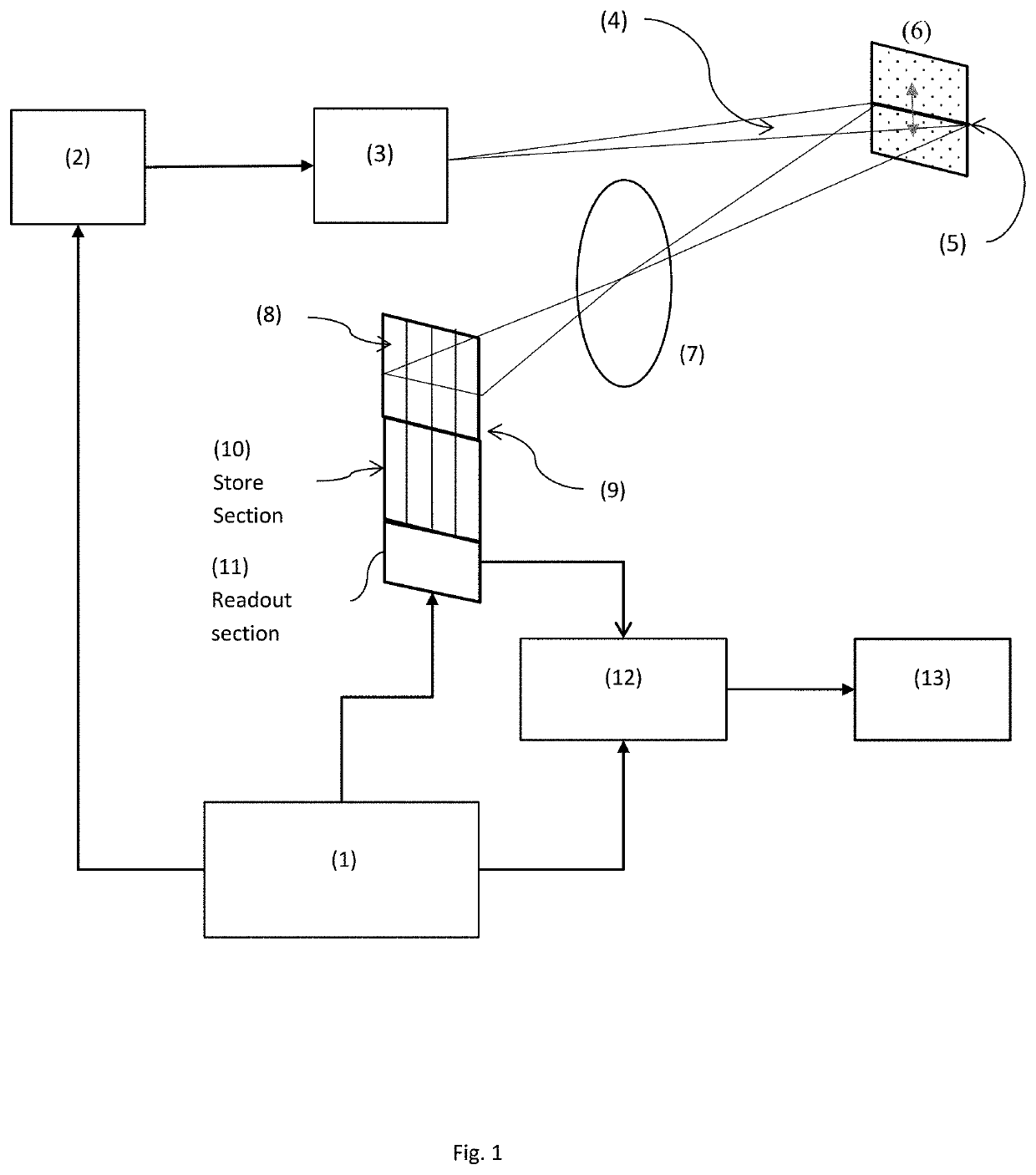
[0059]One embodiment is shown in FIG. 1.

[0060]Control electronics (1) are configured to control light source (2) and associated optical system (3) to emit a pattern of light with a pre-defined combination of spatial and temporal characteristics into the far field.

[0061]In the simplest embodiment shown in FIG. 1, the spatial distribution of the emitted light is a fan beam (4) whose location in a direction orthogonal to the long axis of the beam is adjustable under control of the control electronics (1) and the temporal characteristics of the light are a short pulse, emitted at a time T0, also under control of the control electronics (1).

[0062]This combination of spatial and temporal characteristics will create a pulsed stripe ...


PUM


Abstract

A time of flight sensor has an image region (8) and a storage region (10) on a device which may be a CCD. A pulse of light illuminates an object, and an image illumination stripe is recorded on the image region. In a distance determining step, the image region is clocked after emitting the pulse of light and the row in which the image illumination stripe is illuminated gives a measure of the distance to the object. The apparatus can self calibrate by emitting a pulse of light without clocking the image region.

Description

FIELD OF INVENTION[0001]The invention relates to a time of flight distance sensor and method of use.BACKGROUND TO THE INVENTION[0002]Accurate and fast surface profile measurement is a fundamental requirement for many applications including industrial metrology, machine guarding and safety systems as well as automotive driver assistance and collision warning systems.[0003]Many different approaches have been developed over the years with the objective of providing a low cost yet high performance surface profile solution.[0004]Sensors based on triangulation measurement techniques using structured illumination patterns have proven to be very successful in short range applications such as gesture control, gaming and industrial metrology but their inability to cope with high ambient light levels have tended to restrict their use to indoor applications or applications where the overall illumination level can be controlled.[0005]To overcome these constraints, much effort has been expended o...

Claims


Application Information

Patent Timeline
IPC IPC(8): G01S7/486G01S7/497G01S7/4863G01S7/4865G01S17/894
CPCG01S7/4865G01S7/4863G01S7/497G01S17/894
Inventor MORCOM, CHRISTOPHER JOHN
Owner PHOTONIC VISION LTD
Why Eureka
Try Eureka