Projection display

a projection display and display technology, applied in the field of projection displays, can solve problems such as light leakage into, and achieve the effects of reducing the contrast ratio of the micromirror, minimizing light diffraction, and minimizing the cost of illumination optics

Inactive Publication Date: 2005-02-10
TEXAS INSTR INC +1
View PDF99 Cites 46 Cited by
  • Summary
  • Abstract
  • Description
  • Claims
  • Application Information

AI Technical Summary

Benefits of technology

[0002] In order to minimize light diffraction along the direction of switching and in particular light diffraction into the acceptance cone of the collection optics, in the present invention, micromirrors are provided which are not rectangular (“rectangular” as used herein including square micromirrors). Diffraction as referred to herein, denotes the scattering of light off of a periodic structure, where the light is not necessarily monochromatic or phase coherent. Also, in order to minimize the cost of the illumination optics and the size of the display unit of the present invention, the light source is placed orthogonal to the rows (or columns) of the array, and / or the light source is placed orthogonal to a side of the frame defining the active area of the array. The incident light beam, though orthogonal to the rows (or columns) and / or side of the active area, should not, however, be orthogonal to sides of the individual micromirrors in the array. Orthogonal sides cause incident light to diffract along the direction of micromirror switching, and result in light ‘leakage’ into the ‘on’ state even if the micromirror is in the ‘off’ state. This light diffraction decreases the contrast ratio of the micromirror.
[0003] The present invention optimizes the contrast ratio of the micromirror array so that when micromirrors are in their ‘off’ state they send minimal light to the spatial region where light is directed when micromirrors are in their ‘on’ state. More specifically, the present invention comprises a particularly located light source and incident light beam and particularly designed micromirrors in the array, which minimize light diffracted into the acceptance cone of the projection (or viewing) optics, so as to provide an improved contrast ratio. The arrangement and design of the present invention also minimizes non-reflective areas in the array, by allowing for a tight fit of micromirrors and a large fill factor with low diffraction from the ‘off’ to the ‘on’ state, even when the array is illuminated along the axes of micromirror periodicity. Namely, the design optimizes contrast ratio through angular sides non-parallel to the micromirror's axis of rotation and optimizes fill factor through hinges that require a relatively small amount of area and allow neighboring micromirrors to tile together with little wasted non-reflective area. The micromirror structures and shapes of various examples of the invention also decrease cross talk between adjacent micromirrors when the micromirrors are deflected electrostatically.
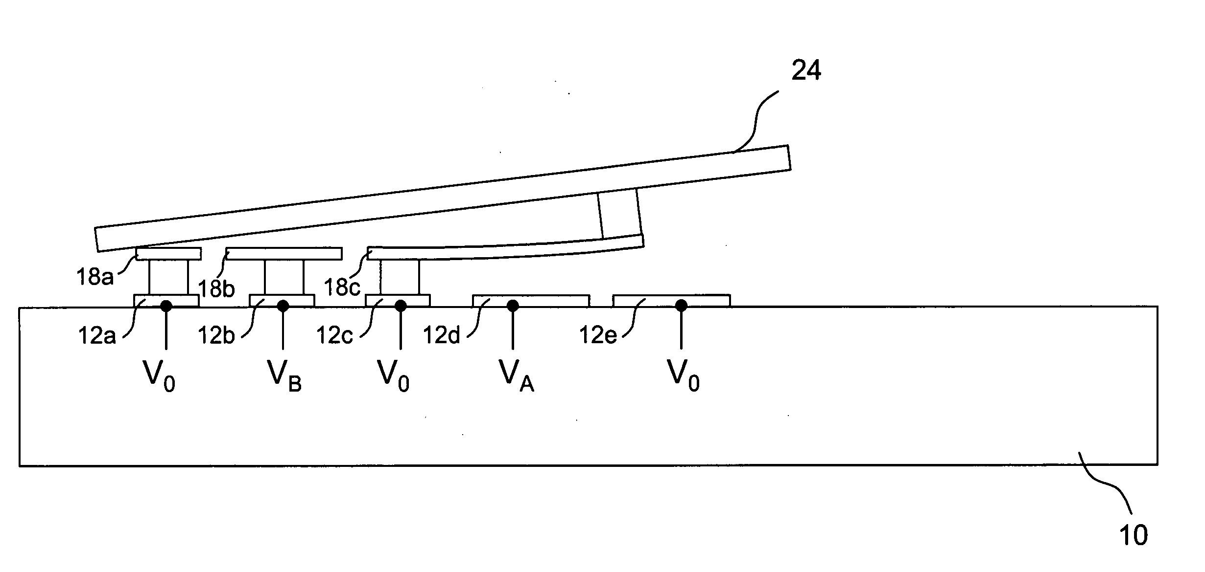
[0004] Another aspect of the invention is a micromirror array where the individual micromirrors tilt asymmetrically around a flat or non-deflected state. By making the ‘off’ state of the micromirrors at an angle less than the opposite angle of the micromirrors in the ‘on’ state, a) diffracted light from the edges of the micromirrors that enters the collection optics is minimized, b) and light that is scattered from beneath the micromirrors that enters the collection optics is also minimized, c) travel of the micromirrors is decreased thus minimizing the possibility of adjacent micromirrors hitting each other, which in turn allows for reducing the gap between micromirrors and increasing fill factor of the micromirror array, and d) the angle of deflection of the micromirrors can be increased to a greater extent than micromirror array arrangements with the same angle of deflection for the on and off states.
[0005] Another aspect of the invention is a package for the micromirror array that has a light transmissive portion of the package that is not parallel with the substrate upon which the micromirrors are formed. The light transmissive portion can be any suitable material such as a plate of glass, quartz or polymer, and allows for directing specular reflection from the light transmissive substrate in directions other than those that result from a parallel light transmissive plate in the packaging. Preferably the specular reflection is directed sufficiently far from the collection optics so that an increase in the size of the illumination cone will keep the specular reflection from entering the collection optics.

Problems solved by technology

Orthogonal sides cause incident light to diffract along the direction of micromirror switching, and result in light ‘leakage’ into the ‘on’ state even if the micromirror is in the ‘off’ state.

Method used


Image

  • Projection display
  • Projection display
  • Projection display

Examples


Embodiment Construction

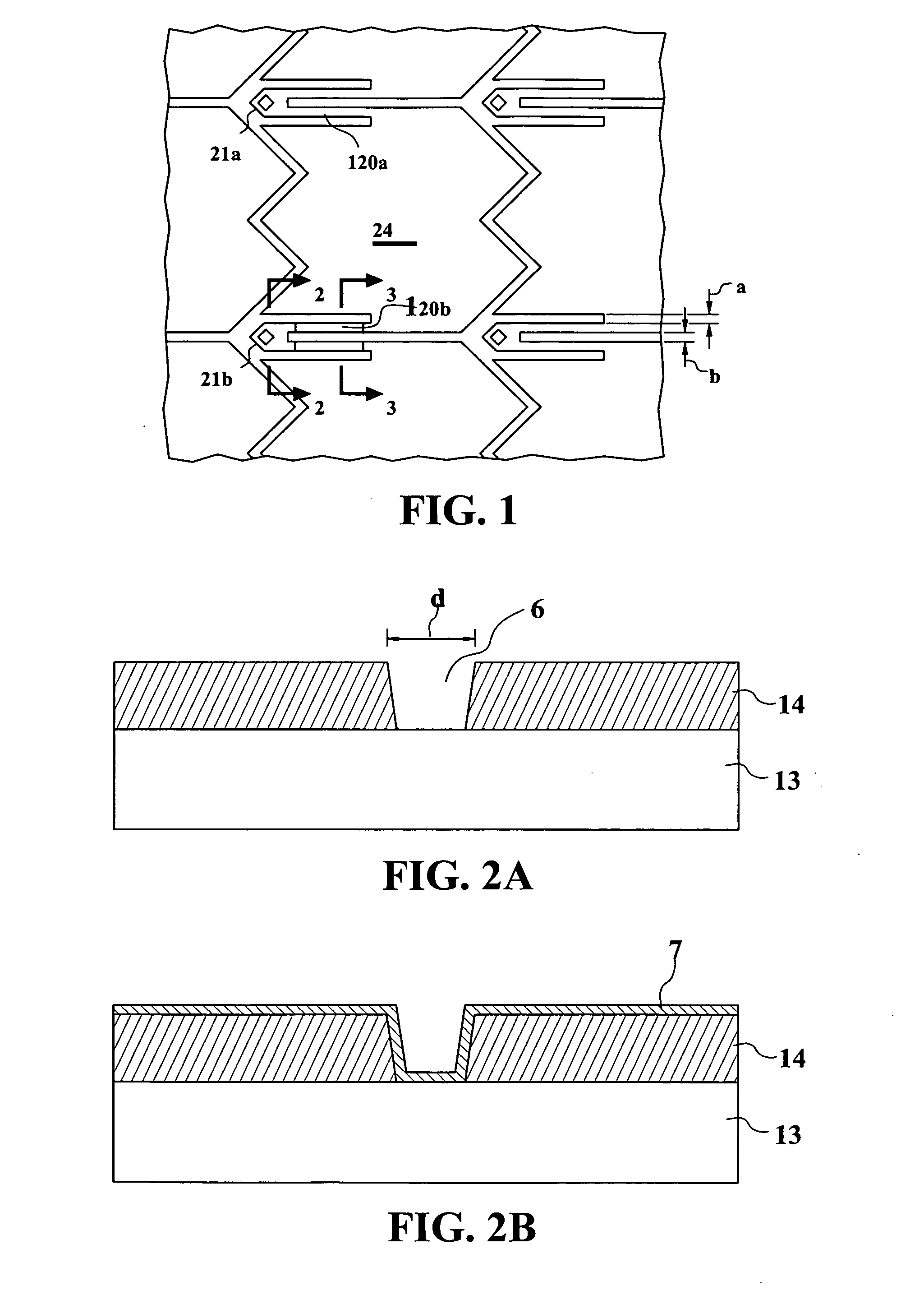
[0055] Processes for microfabricating a movable micromirror or micromirror array are disclosed in U.S. Pat. Nos. 5,835,256 and 6,046,840 both to Huibers, the subject matter of each being incorporated herein by reference. A similar process for forming the micromirrors of the present invention is illustrated in FIGS. 1 to 3. FIG. 1 is a top view of one embodiment of the micromirrors of the present invention. As can be seen in FIG. 1, posts 21a and 21b hold micromirror plate 24 via hinges 120a and 120b above a lower substrate having electrodes thereon (not shown) for causing deflection of micromirror plate 24. Though not shown in FIG. 1, and as will be discussed further herein, thousands or even millions of micromirrors 24 can be provided in an array for reflecting light incident thereon and projecting an image to a viewer or target / screen.

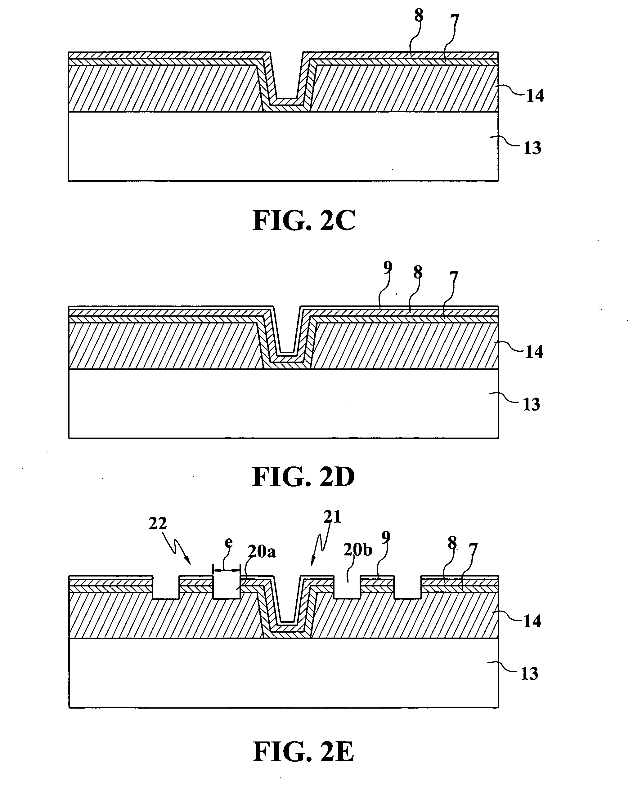
[0056] Micromirror 24, and the other micromirrors in the array, can be fabricated by many different methods. One method is illustrated in FIGS. 2A ...


PUM


Abstract

In order to minimize light diffraction along the direction of switching and more particularly light diffraction into the acceptance cone of the collection optics, in the present invention, micromirrors are provided which are not rectangular. Also, in order to minimize the cost of the illumination optics and the size of the display unit of the present invention, the light source is placed orthogonal to the rows (or columns) of the array, and / or the light source is placed orthogonal to a side of the frame defining the active area of the array. The incident light beam, though orthogonal to the sides of the active area, is not however, orthogonal to any substantial portion of sides of the individual micromirrors in the array. Orthogonal sides cause incident light to diffract along the direction of micromirror switching, and result in light ‘leakage’ into the ‘on’ state even if the micromirror is in the ‘off’ state. This light diffraction decreases the contrast ratio of the micromirror. The micromirrors of the present invention result in an improved contrast ratio, and the arrangement of the light source to micromirror array in the present invention results in a more compact system. Another feature of the invention is the ability of the micromirrors to pivot in opposite direction to on and off positions (the on position directing light to collection optics), where the movement to the on position is greater than movement to the off position. A further feature of the invention is a package for the micromirror array, the package having a window that is not parallel to the substrate upon which the micromirrors are formed. One example of the invention includes all the above features.

Description

BACKGROUND [0001] This is a continuation of Ser. No. 10 / 343,307 filed Jan. 29, 2003, which is US National Phase of PCT / US01 / 24332 filed Aug. 3, 2001, which claims priority from Ser. No. 09 / 631,536 filed Aug. 3, 2000 (now U.S. Pat. No. 6,529,310) and 60 / 229,246 filed Aug. 30, 2000, and Ser. No. 09 / 732,445 filed Dec. 7, 2000 (now U.S. Pat. No. 6,523,961), each of the above applications being incorporated herein by reference.SUMMARY OF THE INVENTION [0002] In order to minimize light diffraction along the direction of switching and in particular light diffraction into the acceptance cone of the collection optics, in the present invention, micromirrors are provided which are not rectangular (“rectangular” as used herein including square micromirrors). Diffraction as referred to herein, denotes the scattering of light off of a periodic structure, where the light is not necessarily monochromatic or phase coherent. Also, in order to minimize the cost of the illumination optics and the size ...

Claims


Application Information

Patent Timeline
Patent Type & Authority Applications(United States)
IPC IPC(8): B81B3/00G02B26/08G03B21/28
CPCG02B26/0841Y10S359/904G03B21/28
Inventor HUIBERS, ANDREW G.
Owner TEXAS INSTR INC
Why Eureka
Try Eureka