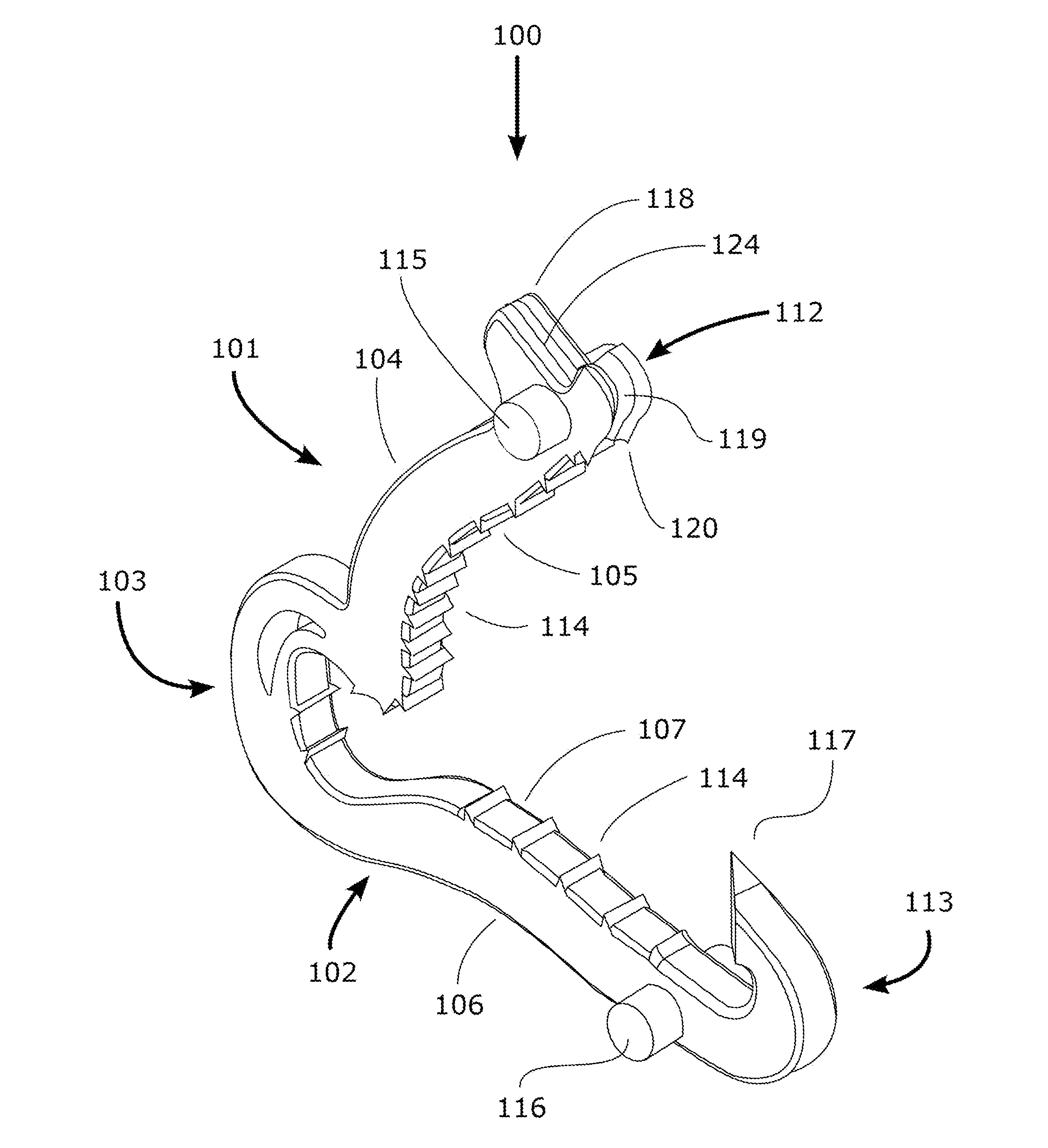
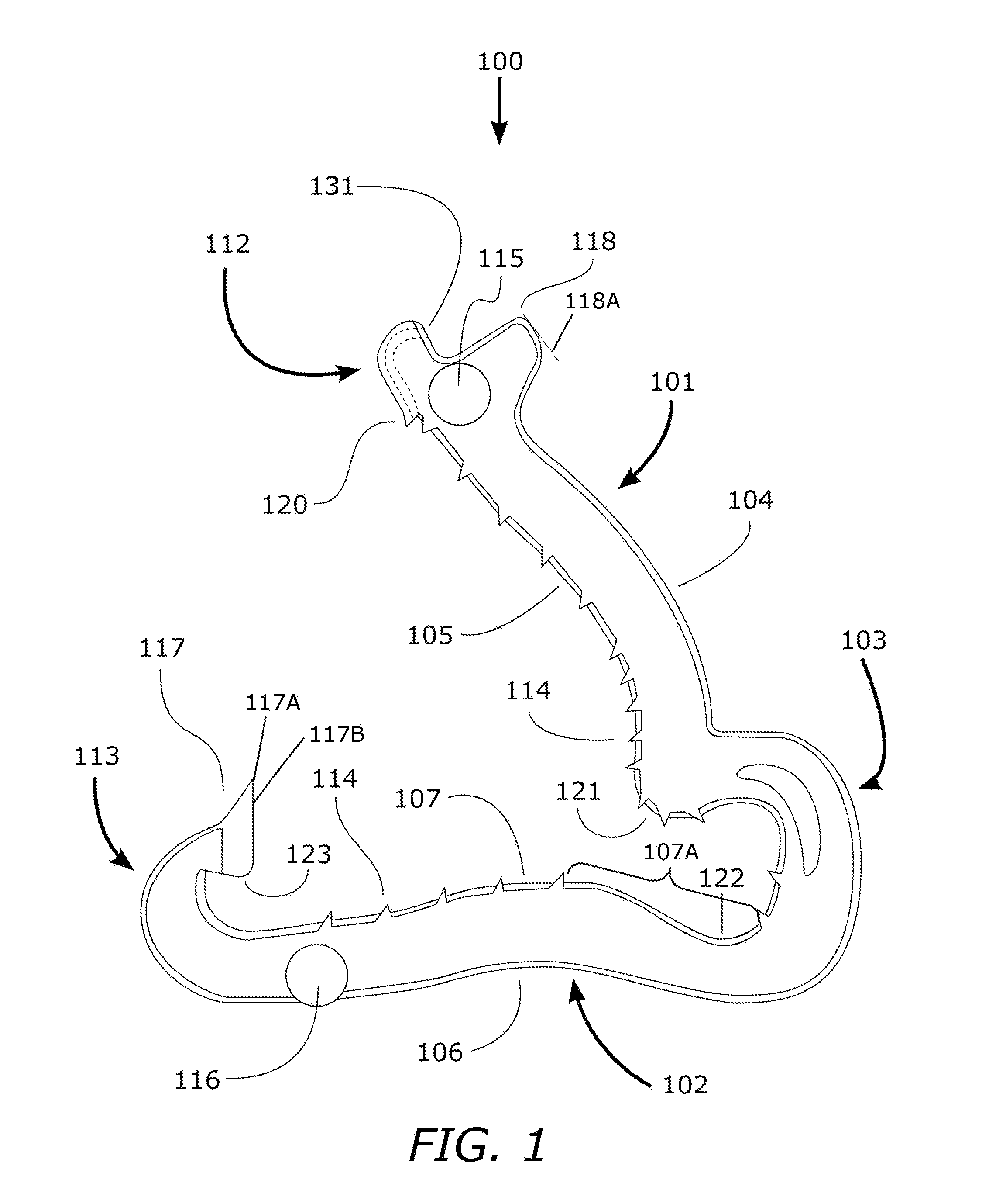
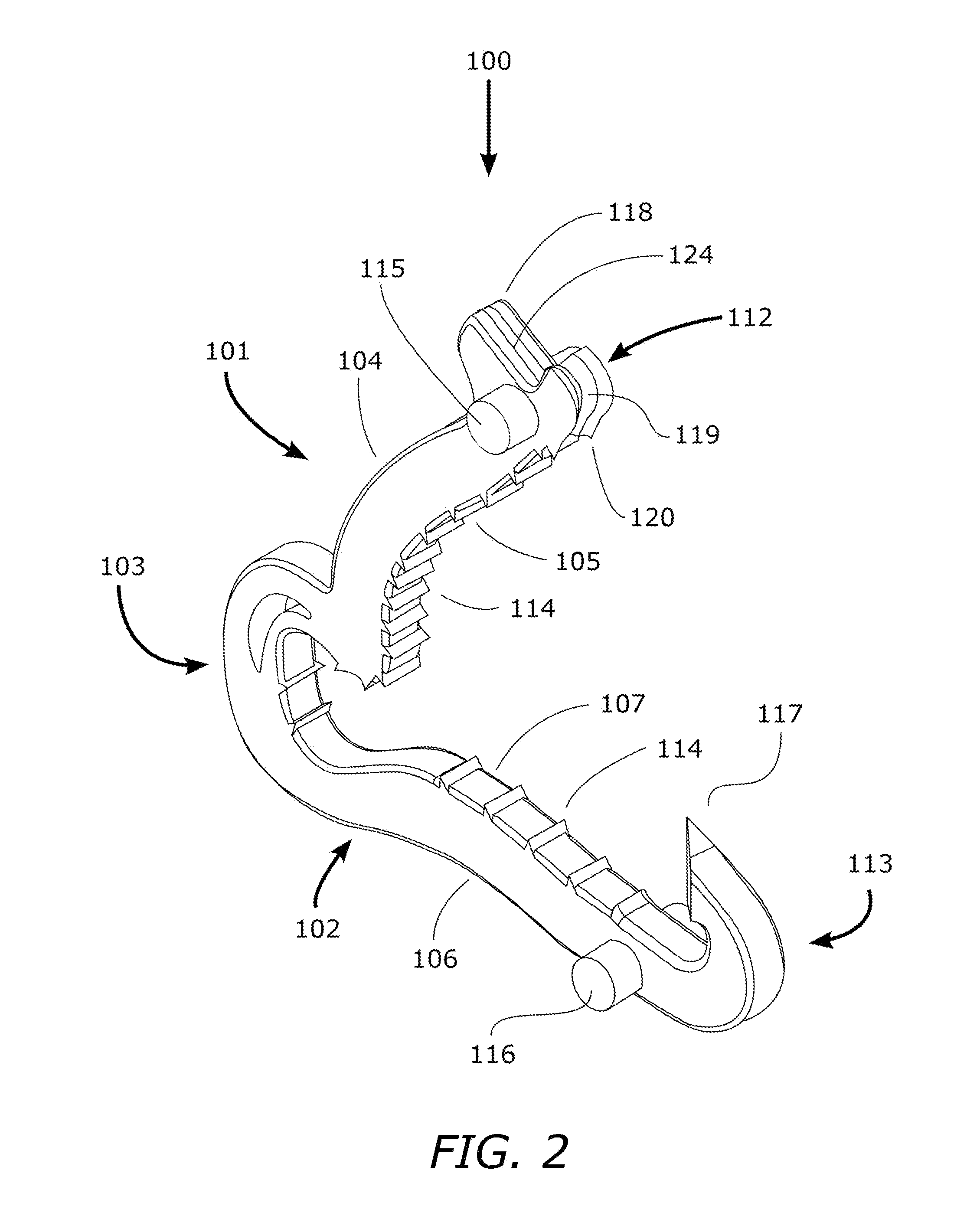
Ligation clip

a technology of ligation and clip, which is applied in the field of ligation clip, can solve the problems of limited freedom of movement in the use of minimally invasive surgical techniques, limited use of metallic clips, and limited use of design and material components of metallic clips

Active Publication Date: 2014-08-28
TELEFLEX LIFE SCI PTE LTD
View PDF53 Cites 48 Cited by
  • Summary
  • Abstract
  • Description
  • Claims
  • Application Information

AI Technical Summary

Problems solved by technology

The space and time needed for this process limits the efficacy of suture-based ligation techniques, particularly in endoscopic or laparoscopic surgeries.
The restrictions to freedom of movement incumbent in the use of minimally invasive surgical techniques present a significant challenge to the surgeon when ligating target vessels or structures with sutures.
While functional, the design and material components of metallic clips limit their use under the state of the art.
For example, metallic clips cannot be used in patients that may undergo magnetic resonance imaging (MRI) or computed tomography (CT) as the clips can interfere with the signals used in those imaging modalities.
Furthermore, since the metallic clips are closed via permanent deformation of the clip itself, an inherent limit is placed on the size vessel a given size of metallic clip can close (i.e. the high magnitude of deformation required to close a metallic clip about a larger diameter vessel may weaken the metal and induce a break or other failure in the structure of the clip) resulting in potentially catastrophic clinical consequences.
When the distal portion of the second jaw contacts the distal portion of the first jaw, the distal portions may slide relative to each other, which may cause the hinge portion to deflect.

Method used


Image

  • Ligation clip
  • Ligation clip
  • Ligation clip

Examples


Embodiment Construction

[0038]Examples of clips and of methods of making and using the clips are described. Depending on what feature or features are incorporated in a given structure or a given method, benefits can be achieved in the structure or the method.

[0039]These and other benefits will become more apparent with consideration of the description of the examples herein. However, it should be understood that not all of the benefits or features discussed with respect to a particular example must be incorporated into a tool, component or method in order to achieve one or more benefits contemplated by these examples. Additionally, it should be understood that features of the examples can be incorporated into a clip, component or method to achieve some measure of a given benefit even though the benefit may not be optimal compared to other possible configurations. For example, one or more benefits may not be optimized for a given configuration in order to achieve cost reductions, efficiencies or for other r...


PUM


Abstract

A surgical ligation clip and method of operation are described and include a top jaw member and bottom jaw member joined at a hinge section for movement about the hinge section. The hinge section can be offset or space laterally from one or both of the jaw members. Teeth arrangements and distributions are also described, as well as closing and jaw ends engagement configurations, for example for more easily engaging / piercing connective or other tissue.

Description

CROSS REFERENCE TO RELATED APPLICATIONS[0001]This is a non-provisional of U.S. 61 / 549,740, filed Oct. 20, 2011, the content of which is incorporated herein by reference.BACKGROUND OF THE INVENTIONS[0002]Ligation of vessels or other anatomical structures is a common step in a large number of surgical procedures. Traditionally, a ligation procedure comprises the placement of a suture about the target vessel or anatomical structure (e.g. artery, vein, duct, Fallopian tube, etc.) and tying off the suture to close the vessel, conduit or structure. The effective use of sutures to accomplish this procedure relies on the skillful execution of complex knots using a needle and thread. The space and time needed for this process limits the efficacy of suture-based ligation techniques, particularly in endoscopic or laparoscopic surgeries. The restrictions to freedom of movement incumbent in the use of minimally invasive surgical techniques present a significant challenge to the surgeon when liga...

Claims


Application Information

Patent Timeline
Patent Type & Authority Applications(United States)
IPC IPC(8): A61B17/122
CPCA61B17/122A61B17/1285
Inventor BAGAOISAN, CELSOPAI, SURESHDREHER, JAMESTAMADDON, KIRK
Owner TELEFLEX LIFE SCI PTE LTD
Why Eureka
Try Eureka