Vibrating member for a brushless vacuum cleaner

Inactive Publication Date: 2014-09-11
ZENITH TECH
View PDF3 Cites 1 Cited by
  • Summary
  • Abstract
  • Description
  • Claims
  • Application Information

AI Technical Summary

Benefits of technology

[0008]A brushless vacuum cleaner in accordance with exemplary embodiments of the present invention provides a vibrating member disposed in a vacuum cleaner head to facilitate removing dirt and debris from a surface to be cleaned. Dirt

Problems solved by technology

However, ground-in dirt is frequently encountered when cleaning carpets or other textured surfaces, and reliance on suction for removal of such ground-in dirt has proven to be unsatisfactory.
However, th

Method used


Image

  • Vibrating member for a brushless vacuum cleaner
  • Vibrating member for a brushless vacuum cleaner
  • Vibrating member for a brushless vacuum cleaner

Examples


Embodiment Construction

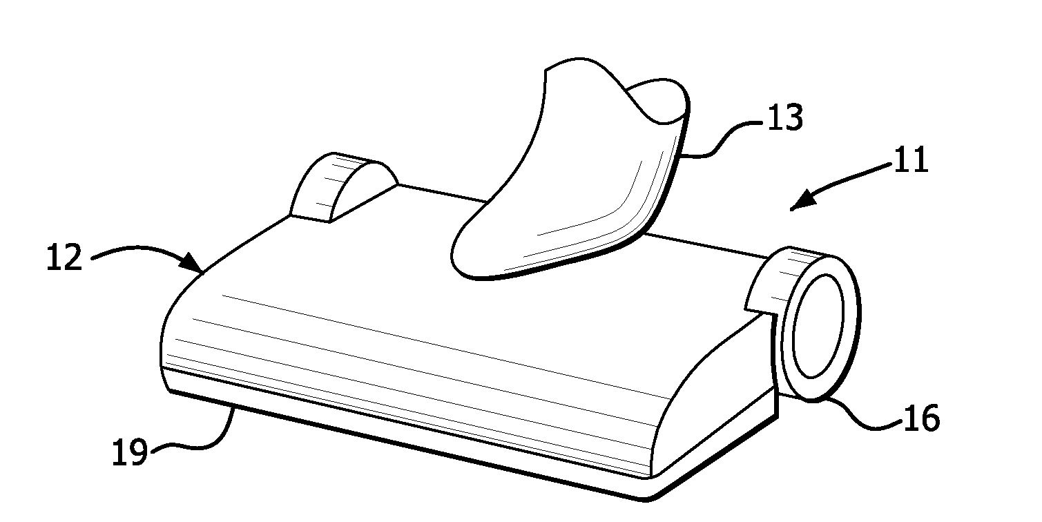
[0038]As shown in FIGS. 1-24, a brushless vacuum cleaner in accordance with exemplary embodiments of the present invention includes a vibrating member to facilitate removing dirt and debris from a surface to be cleaned. The vacuum cleaner can be any type of device employing suction to clean, including, but not limited to, upright, canister and handheld vacuum cleaners. The following description refers to a canister style vacuum cleaner.

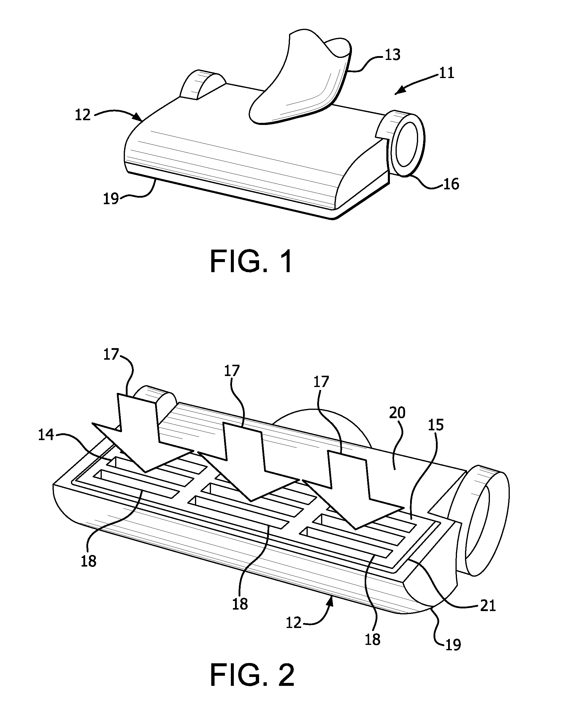
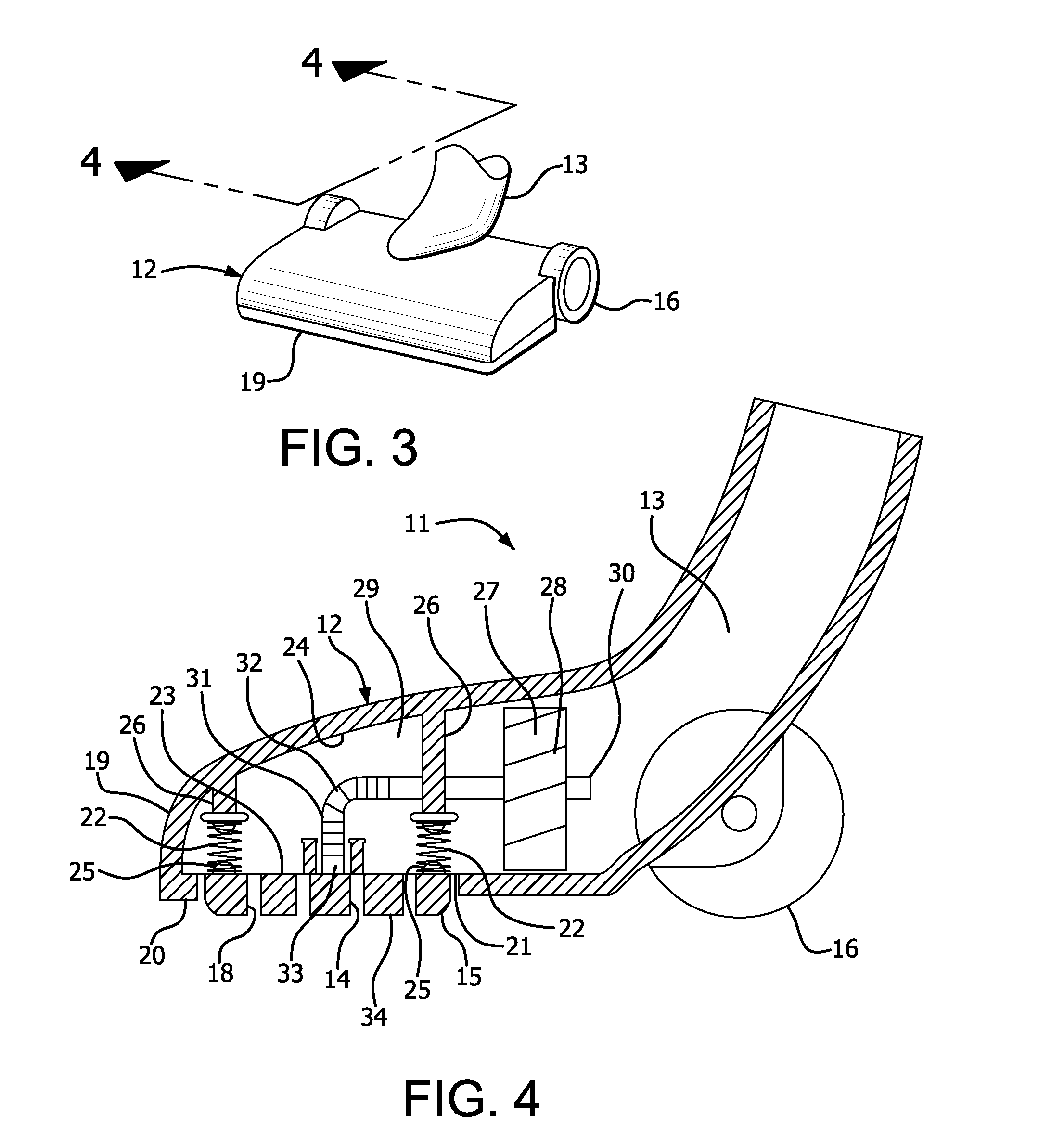
[0039]A motor and a dirt and debris collector of a canister style vacuum cleaner 11 are housed in a separate unit (such as body 512 of FIG. 22), which is connected to a vacuum head 12 by a flexible hose 13, as shown in FIGS. 1 and 4. Wheels 16 connected to a housing 19 of the vacuum head 12 facilitate moving the vacuum head across a surface to be cleaned.

[0040]The vacuum cleaner 11 of the present invention does not include a brush roll in the vacuum head 12, as shown in FIGS. 2 and 4. The motor creates a partial vacuum, thereby creating a suction forc...


PUM


Abstract

A vacuum cleaner includes a vacuum head having a housing and a vibrating member connected to the housing. A suction inlet draws dirt and debris into the vacuum head. Vibration of the vibrating member facilitates drawing the dirt and debris into the vacuum head through the suction inlet.

Description

CROSS REFERENCE TO RELATED APPLICATION[0001]This application claims the benefit under 35 U.S.C. §119(e) of U.S. Provisional Application Ser. No. 61 / 775,268, filed Mar. 8, 2013, which is hereby incorporated by reference in its entirety.FIELD OF THE INVENTION[0002]The present invention relates to a brushless vacuum cleaner having a vibrating member to facilitate removing dirt and debris from a surface to be cleaned. More particularly, the present invention relates to a brushless vacuum cleaner having a vibrating member vibrated by air drawn into a vacuum head. Still more particularly, the present invention relates to a brushless vacuum cleaner having an impeller for vibrating a vibrating member in which the impeller is driven by air passing therethrough.BACKGROUND OF THE INVENTION[0003]Conventional vacuum cleaners typically use a suction nozzle that is movable across a surface to be cleaned. The suction created at an inlet in the nozzle results in the removal of dirt and debris accumu...

Claims


Application Information

Patent Timeline
IPC IPC(8): A47L9/04
CPCA47L9/0483
Inventor BOSSES, MARK D.
Owner ZENITH TECH
Why Eureka
Try Eureka