Flexible LED Panel System

Active Publication Date: 2014-09-11
BYRD JEREMY
View PDF9 Cites 3 Cited by
  • Summary
  • Abstract
  • Description
  • Claims
  • Application Information

AI Technical Summary

Benefits of technology

This patent describes a technology where the upper and lower rigging bars are mounted flush with the last rows of LED pixels, which results in a seamless display when multiple panels are connected.

Problems solved by technology

While such panels are useful in many situations, they lack certain features regarding electrical connections, rigging, and portability which would make them more useable and desirable.

Method used


Image

  • Flexible LED Panel System
  • Flexible LED Panel System
  • Flexible LED Panel System

Examples


Embodiment Construction

[0012]Before the subject invention is further described, it is to be understood that the invention is not limited to the particular embodiments of the invention described below, as variations of the particular embodiments may be made and still fall within the scope of the appended claims. It is also to be understood that the terminology employed is for the purpose of describing particular embodiments, and is not intended to be limiting. Instead, the scope of the present invention will be established by the appended claims.

[0013]In this specification and the appended claims, the singular forms “a,”“an,” and “the” include plural reference unless the context clearly dictates otherwise. Unless defined otherwise, all technical and scientific terms used herein have the same meaning as commonly understood to one of ordinary skill in the art to which this invention belongs.

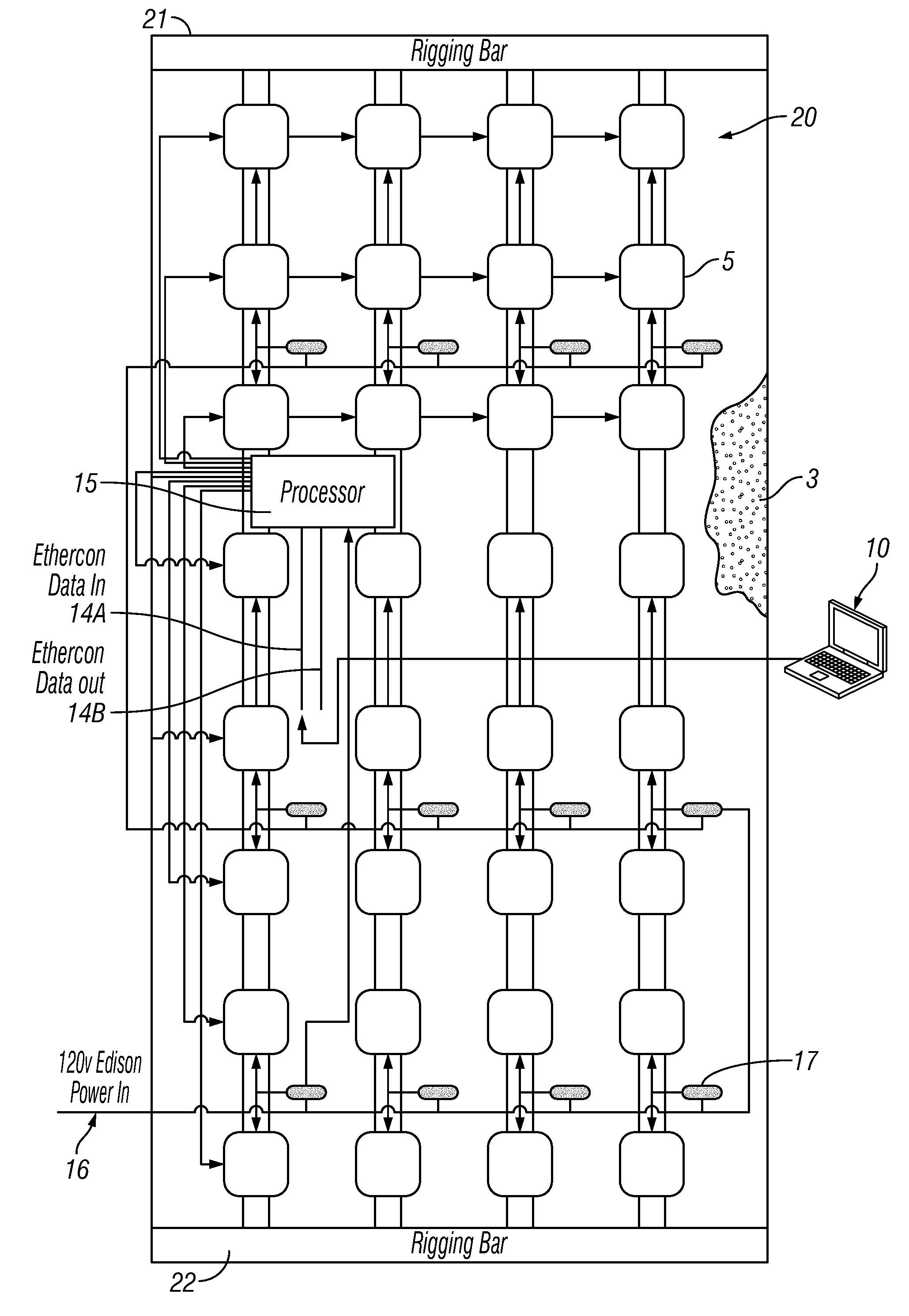
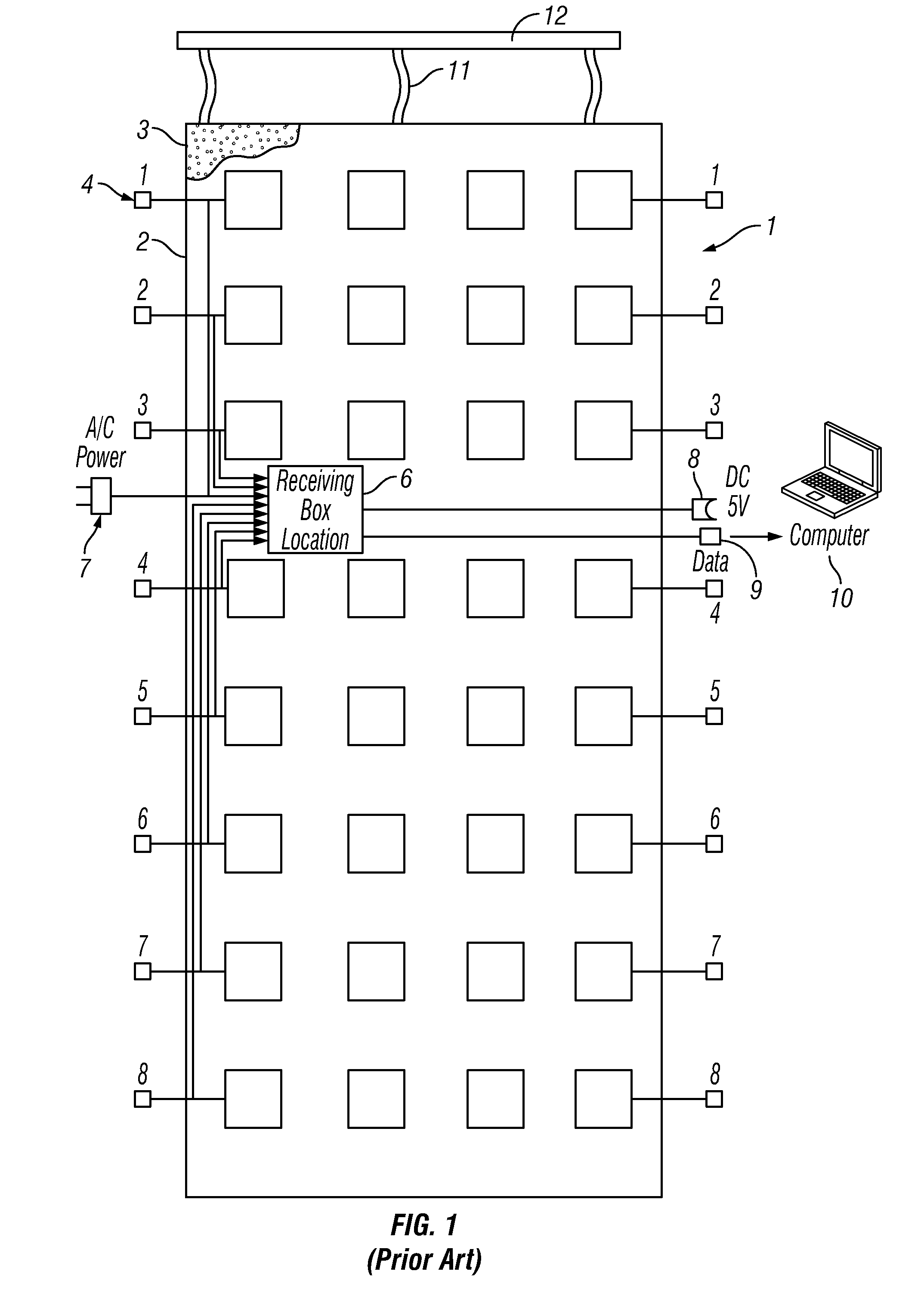
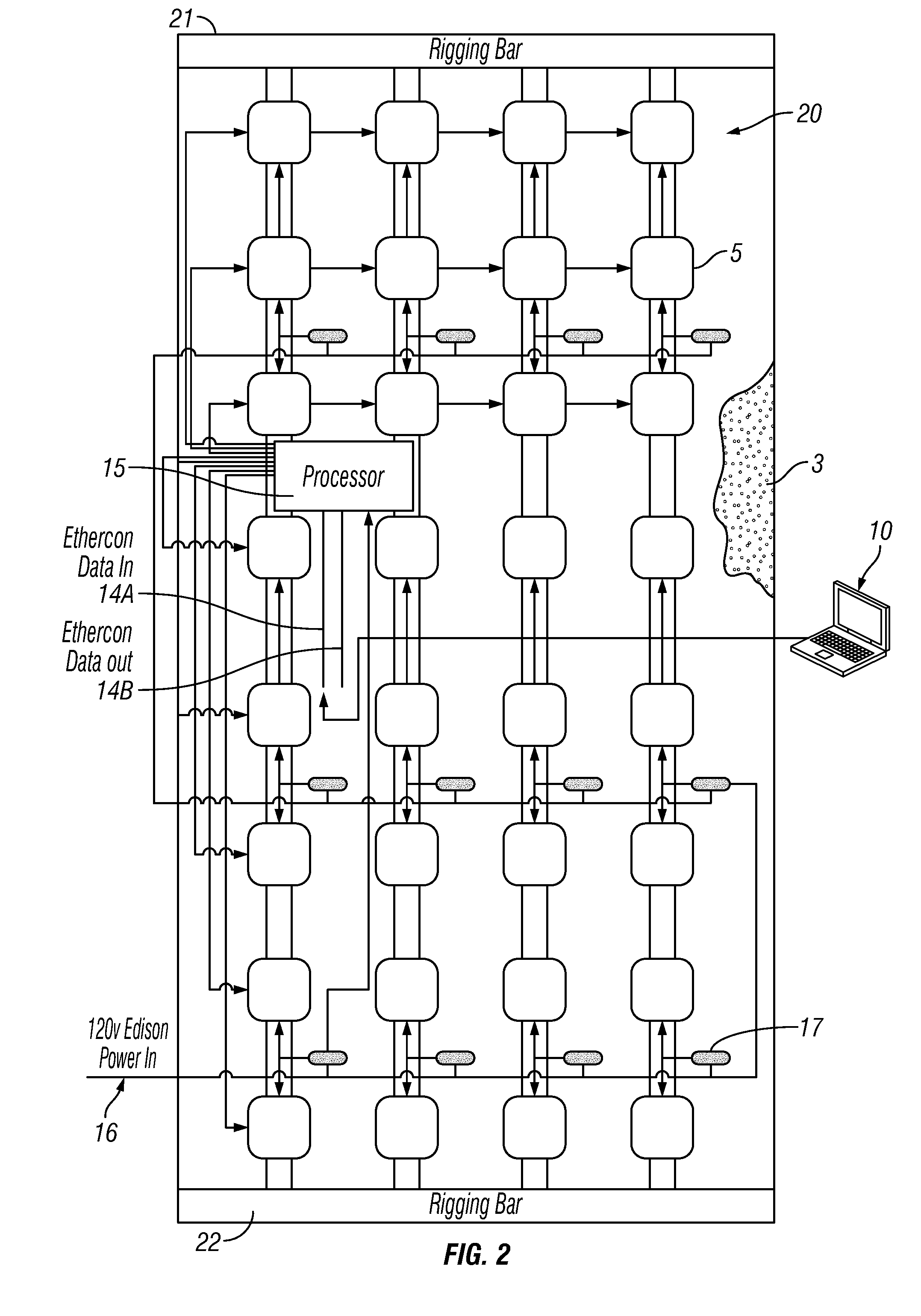
[0014]Turning now to the figures, FIG. 1 depicts a prior art flexible LED display panel 1. The panel 1 comprises a flex...


PUM


Abstract

An improved LED display panel system (1) is provided, comprising a flexible curtain (2) having an array of surface mounted LED's (3) with a pixel density of approximately 2500 pixels per square meter. The panels (1) attach to one another in a vertical orientation employing upper or lower rigging bars (21, 22) which are flush with the last row of LED pixels (3) on each end. All data processing is accomplished inside the panels (1), and a single Ethercon cable connection (14A) is used for data input, and a single Ethercon cable connection (14B) is used for data output.

Description

TECHNICAL FIELD[0001]The present invention relates to large light-emitting diode (LED) devices used to display images, and more particularly to such devices which are flexible and capable of being connected to one another to form a composite display system.BACKGROUND OF THE INVENTION[0002]Current light-emitting diode (LED) panels used in the entertainment industry provide users with a display for either static or moving images. While such panels are useful in many situations, they lack certain features regarding electrical connections, rigging, and portability which would make them more useable and desirable.SUMMARY OF THE INVENTION[0003]A light emitting diode (LED) display panel, comprising a flexible curtain having a plurality of LED's; a plurality of data boxes, wherein each of the data boxes is electronically connected to a predetermined array of LED's, and wherein each of the data boxes is also electronically connected to a predetermined number of other data boxes; a processor ...

Claims


Application Information

Patent Timeline
IPC IPC(8): G09G3/20G09G3/32G06F1/16
CPCG09G3/2088G06F1/1652G09G3/32G09G2300/0426G09G2380/02G09G2340/14G09G2354/00G09G2360/06G09G2320/02G09F9/33G09G3/035
Inventor BYRD, JEREMY
Owner BYRD JEREMY
Why Eureka
Try Eureka