Optimized distribution of light extraction from an edge lit light source

a technology of edge lit light source and distribution method, which is applied in the direction of electric discharge tube/lamp manufacture, lighting and heating apparatus, instruments, etc., can solve the problems of non-uniform light emission, non-uniform intensity light emission, and non-uniformity, and achieve reliable and easy-to-use methods , uniform illumination

Inactive Publication Date: 2010-07-27
BRYTER TECH
View PDF13 Cites 43 Cited by
  • Summary
  • Abstract
  • Description
  • Claims
  • Application Information

AI Technical Summary

Benefits of technology

[0006]To solve one or more of the problems set forth above, an exemplary edge-lit panel is provided featuring an extractor pattern that produces uniform illumination for an image. A reliable and easy-to-use method for adjusting the density of extractor pattern pixels is also provided to achieve such uniform illumination.
[0007]An exemplary edge-lit sign according to principles of the invention includes a solid panel of optical transmission medium having a first surface, a second surface opposite the first surface, and a plurality of edges. The plurality of edges includes at least one illuminated edge and at least one unlit edge. Each unlit edge is coated with a coating that prevents light emission therefrom. A light source provided along the illuminated edge transmits light into the panel through the illuminated edge. An extractor pattern formed on the first surface or the second surface of the pane includes extractor pixels. The extractor pixels cause light transmitted in the panel to emit from the panel. The extractor pixels per unit area (extractor pixel density) vary with distance from the illuminated edge to achieve a substantially spatially uniform intensity of light emitted from the panel. The unlit edge may be coated with a reflective coating. The light source may be a fluorescent lamp, incandescent lamp, and light emitting diode. A reflective cover may be provided to reflect light emitted from the second surface back into the panel. Optionally, an image may be applied over the extractor pattern. Additionally, several layers of panels may be stacked to achieve a 3D effect.
[0009]Thus, the extractor pattern is comprised of pixels that correspond to a grayscale image. The grayscale image features darker areas as distance increases from the light source. The grayscale image is dithered using a dithering algorithm. Dithering turns each shade of gray into a pattern of black and white pixels that, from a distance, look about the same as the gray. Such pattern is referred to as pixelated because individual pixels may be seen on close inspection, but not from a distance. The result is an image with discrete binary elements and / or elements in shades of gray. If the dithered image contains any gray shades, then the dithered image is converted to black and white, i.e., binary. The binary image exhibits greater pixel density in the areas that corresponded to the darker grayscale areas. The binary image is then applied to the panel to form the extractor pattern. Thus, the extractor pixels correspond to pixels of a binary image derived from a dithered grayscale image, with the darkness of the grayscale image increasing with distance from the light source. By adjusting gray shading darkness of a grayscale image, pixel density can be adjusted to achieve uniform light emission.
[0010]The extractor pattern may include a plurality of zones, including a first zone and a second zone. The first zone is closer than the second zone to the illuminated edge. The extractor pixels per unit area in the second zone may be greater than the extractor pixels per unit area in the first zone to compensate for attenuation and achieve a substantially spatially uniform intensity of light emitted from the panel.

Problems solved by technology

A problem with conventional edge-lit panels is non-uniform light emission.
These effects result in light of non-uniform intensity emitted from the extraction pattern formed on the surface of the sign.
Such non-uniformity is manifested as brightly illuminated regions and poorly illuminated regions of the display.
Consequently, conventional edge-lit signs are limited in size to approximately 8 to 12 inches in dimension from the light source.

Method used


Image

  • Optimized distribution of light extraction from an edge lit light source
  • Optimized distribution of light extraction from an edge lit light source
  • Optimized distribution of light extraction from an edge lit light source

Examples


Embodiment Construction

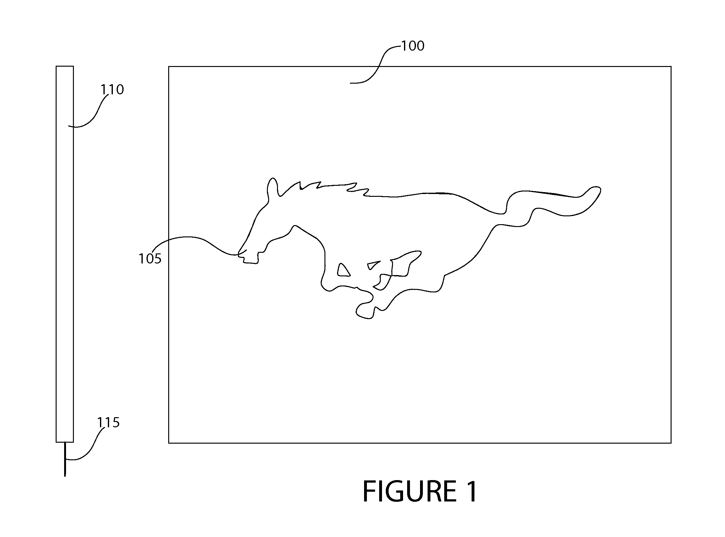
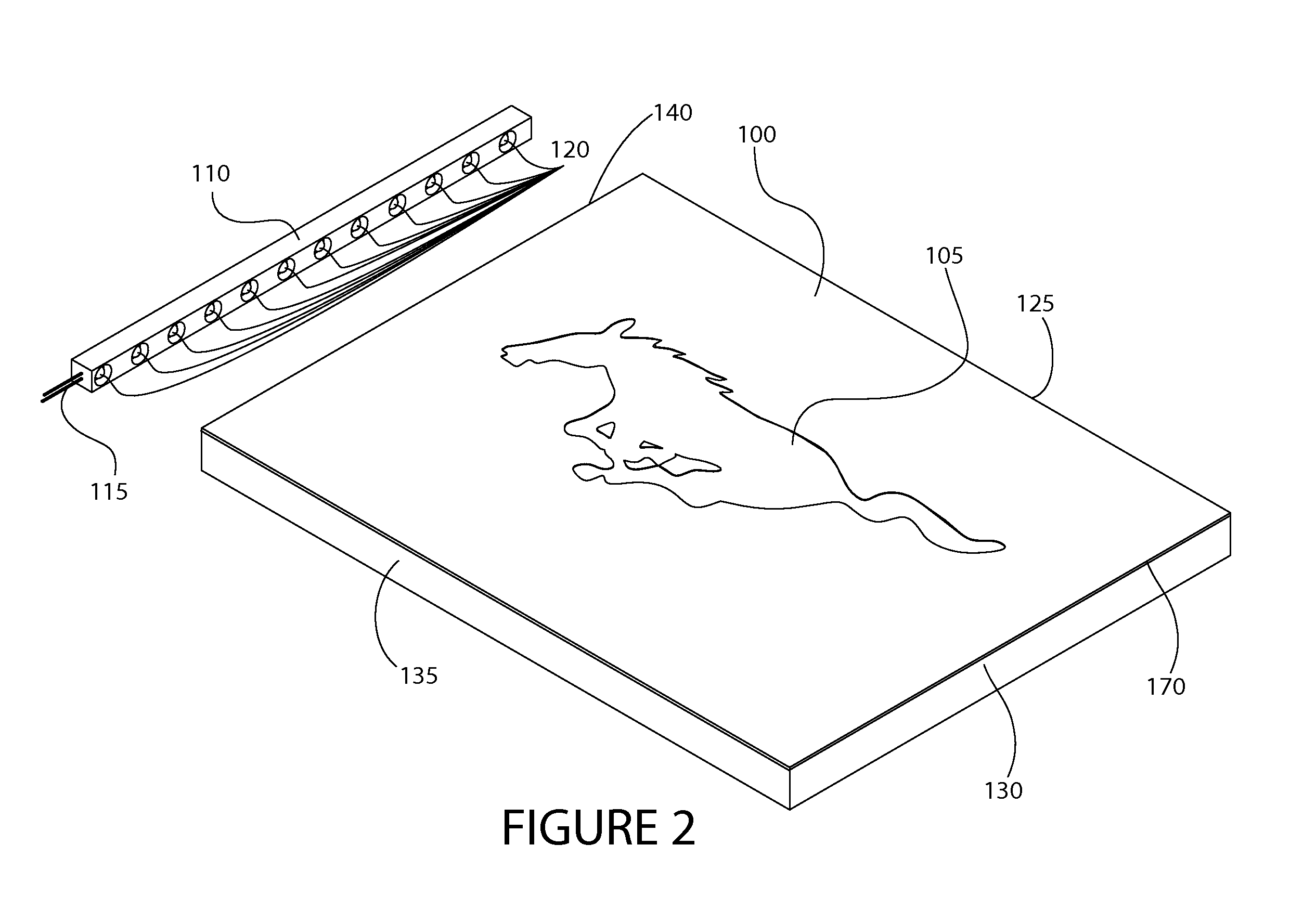
[0022]Referring to the Figures, in which like parts are indicated with the same reference numerals, various views of exemplary edge-lit panel assemblies according to principles of the invention are shown. With particular reference to FIGS. 1 and 2, an exemplary edge-lit sign 100 comprises a panel of optical transmission medium such as glass, plastic (e.g., acrylic), polymethylmethacrylate or any other material suitable for an edge lit sign. In example embodiments, the panel comprises a material having a higher index of refraction than other surrounding materials, such that light is guided within the panel 100 by total internal reflection. Preferably the material is scratch resistant, such as hard (scratch resistant) acrylic. A vinyl layer may be applied to one or more surfaces (e.g., the face) of the panel for scratch resistance. The unlit panel edges 125, 130, 135 may be coated with a reflecting (or absorbing) layer to reduce the amount of light that escapes from the edges. The ref...


PUM


Abstract

An edge-lit panel features extractor patterns that produce uniform illumination. The effective density of extractor pattern pixels is adjusted to achieve uniform illumination. A method of adjusting the effective pixel density of extractor pattern pixels to achieve uniform illumination entails adjusting areas of darkness of a grayscale image, then producing a binary image by dithering the grayscale image, and applying an extractor pattern corresponding to the binary image to a surface of the panel. The extractor pixels correspond to pixels of the binary image derived from a dithered grayscale image, with the darkness of the grayscale image increasing with distance from the light source. Effective pixel density is increased to compensate for attenuated output in dim areas. By adjusting gray shading darkness of a grayscale image, pixel density can be adjusted to achieve uniform light emission. The extractor pixels may be applied using a radiation curable ink, which can be used in high speed inkjet printers that can achieve production speeds. The resulting print is waterproof, embossed and vibrant.

Description

RELATED APPLICATION[0001]This application claims the benefit of priority of U.S. Provisional Application No. 61 / 116,015, filed Nov. 19, 2009, the entire contents of which are incorporated herein and made a part hereof.FIELD OF THE INVENTION[0002]This invention generally relates to signage, and more particularly, to an edge lit panel and method of manufacturing an edge lit panel which optimizes distribution of light extracted from a light source.BACKGROUND[0003]Edge-lit displays, such as edge-lit signs, under-cabinet lighting, ceiling tile lighting, back light (as a replacement for fluorescent bulbs), generally comprise a light source and a treated light transmitting sheet. The light source illuminates one or more edges of the light transmitting sheet. The sheet is composed of internally light-reflective material such as glass or acrylic. Light that enters the sheet is internally reflected, only escaping where the surface has been treated. The treated area is referred to as an extrac...

Claims


Application Information

Patent Timeline
Patent Type & Authority Patents(United States)
IPC IPC(8): F21V7/04
CPCG02B6/006G02B6/0076G09F13/18G09F13/22G02B6/0036G02B6/0043G09F2013/222
Inventor BRYCHELL, JOSEPH
Owner BRYTER TECH
Why Eureka
Try Eureka