Error detection methods in wireless communication systems

a wireless communication system and wireless communication technology, applied in the field of wireless communication systems, can solve the problems of loss or delay of information, low probability of detection, and excessive overhead of using even a length-8 crc, and achieve the effect of low probability of false alarm and high probability of error detection

Inactive Publication Date: 2007-01-09
LUCENT TECH INC +1
View PDF13 Cites 53 Cited by
  • Summary
  • Abstract
  • Description
  • Claims
  • Application Information

AI Technical Summary

Benefits of technology

[0031]An efficient and reliable method of detecting errors in control channels of a wireless communication system is provided in order to ensure that for each UE in the system, the probability of error detection is high and the probability of false alarm is low. In an embodiment, the method decodes at least a portion of a control channel, determines if one or more control channels were successfully received during the decoding, and selects one of the successively received control channels based on at least one calculated metric.
[0033]In an embodiment, the method utilizes a Yamamoto-Itoh (YI) decoding algorithm in order to determine how many HS-SCCH's were successfully received during the decoding step. In another embodiment, a base station appends a parity check code to Part I of each HS-SCCH, and the UE uses the parity check code during decoding in order to determine which of the HS-SCCH's were successfully received. The parity check code may be used with the aforementioned YI algorithm to provide additional reliability, and then the calculated PMD's are used to break any ties, should multiple HS-SCCHs be successfully received.

Problems solved by technology

In most cases, a frame is discarded when the receiver detects an error, which is uncorrectable, in the transmission based on the error detection code.
This results in a loss or delay of information, depending on whether a retransmission is subsequently carried out.
This is an undetected error because the decoded information is erroneous, but the error detection code did not catch the error.
However, in certain applications very few bits need to be transmitted per frame and the overhead from using even a length-8 CRC may be excessive.
A low probability of detection implies wasted resources, since every missed detection event means that the transmission on the corresponding HS-DSCH is wasted.
A false alarm event would cause a UE that is NOT scheduled for a particular transmission to begin buffering data and try to decode the information which would waste battery resources at the UE, for example, due to unnecessary processing.
However, Part I of the HS-SCCH usually contains only about 8 information bits, so to use a 12-bit CRC or greater represents a substantial overhead (>150%).
Furthermore, the number of Part I bits the UE must process is excessive.
This is undesirable, and is essentially the equivalent of processing a peak data rate of 120 kbps just to decode part of the control information
However, whenever the UE descrambles a transmission that was intended for some other UE, the decoder metric is usually low.
Occasionally, due to noise, the incorrect path is chosen over the correct one during one of the aforementioned merging instances.
This results in a decoding error.
If that calculated path metric difference is below a predetermined threshold, then the decoding is considered unreliable, and the UE declares that the transmission on that particular HS-SCCH was not intended for it.

Method used


Image

  • Error detection methods in wireless communication systems
  • Error detection methods in wireless communication systems
  • Error detection methods in wireless communication systems

Examples


Embodiment Construction

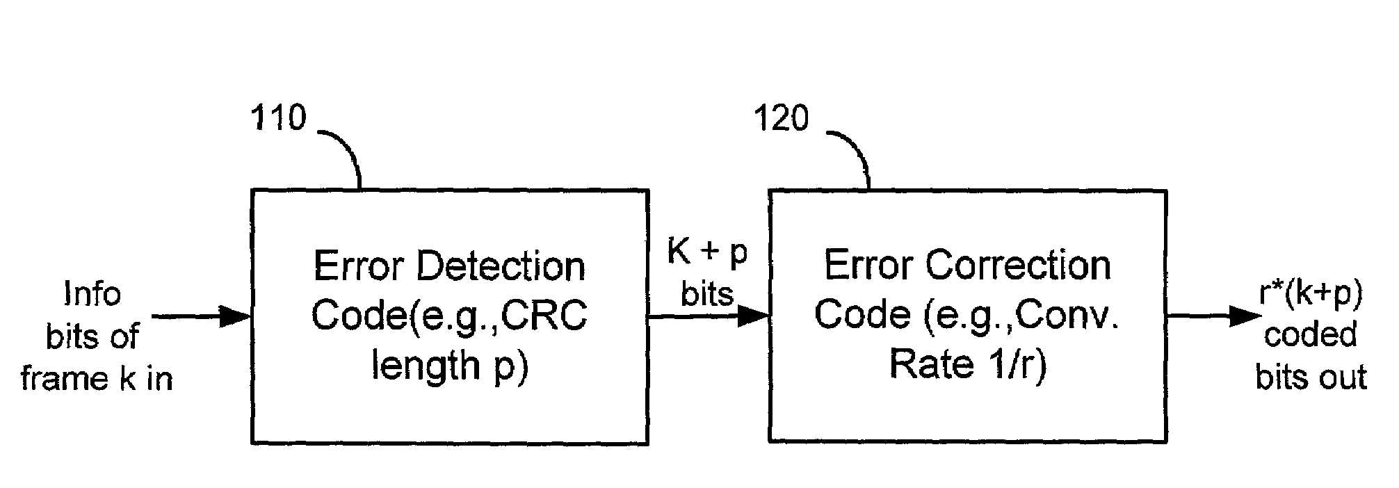
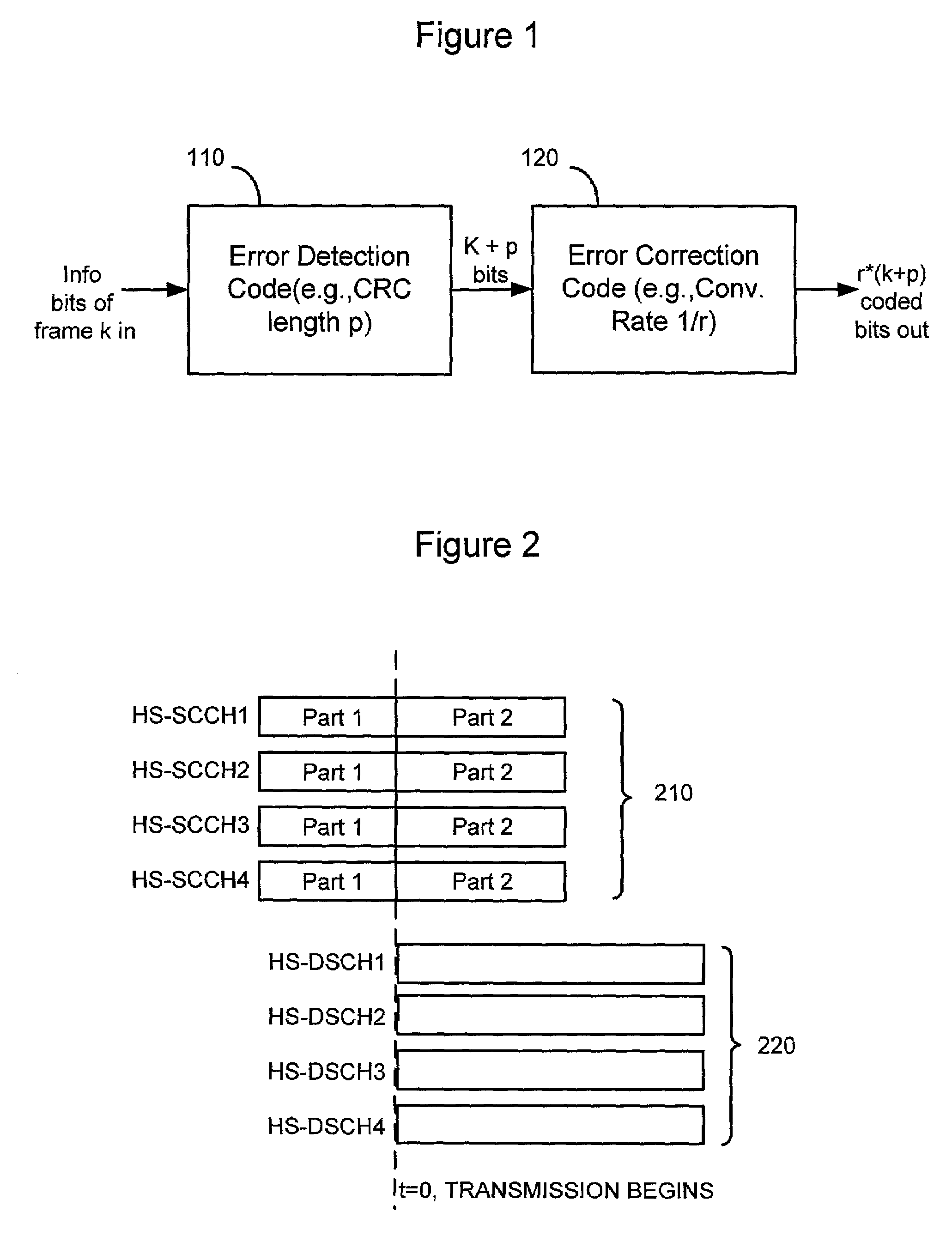
[0047]Although the principles of the invention are particularly well-suited for wireless communications systems based on the well-known High Speed Downlink Packet Access (HSDPA) specification in the Universal Mobile Telecommunication System (UMTS) standard, and will be described in this exemplary context, it should be noted that the embodiments shown and described herein are meant to be illustrative only and not limiting in any way. As such, various modifications will be apparent to those skilled in the art for application to other transmission systems and are contemplated by the teachings herein. Additionally where used below, user equipment (UE) is synonymous to a mobile station in a wireless communication network.

[0048]Accordingly, there is now described a method for detecting errors in control channels of a wireless communication system that overcomes the problems of inadequate error detection and false alarm performance, which are present in the conventional scrambling or EPMD ...


PUM


Abstract

The error detection method includes decoding a portion of each control channel that is simultaneously received by a user equipment (UE) in a wireless communication system. The UE is provided with techniques to determine if one or more of the control channels were successfully received during the decoding step. If more than one control channel was successfully received, the method selects only one of the successfully received control channels based on calculated path metric differences (PMD) that serve as a “tie-breaking” mechanism to select the correct control channel for a particular UE.

Description

BACKGROUND OF THE INVENTION[0001]1. Technical Field[0002]The invention relates generally to wireless communication systems and, more particularly, to error detection methods for evaluating information that is transmitted in control channels of such systems.[0003]2. Description of Related Art[0004]Almost all wireless communication systems employ “frame-based” communication, where a certain number of bits, defined as a frame, are channel encoded together and transmitted. Most systems employ concatenated coding for each frame with an inner error correction code such as a convolutional or Turbo error correction code and an outer error detection code.[0005]FIG. 1 illustrates a process flow for forming a typical concatenated code structure at the transmitter of a base station. As shown, an error detection code is added at 110 to a frame of a data channel, the frame comprising k bits. Typically a cyclic redundancy check (CRC) code, shown here as having a length p, is used as the error dete...

Claims


Application Information

Patent Timeline
Patent Type & Authority Patents(United States)
IPC IPC(8): H03M13/00H04L1/18H03M13/09H03M13/41H03M13/29H03M13/39H04L1/00H04L1/22
CPCH03M13/09H03M13/2975H03M13/39H03M13/41H04L1/0054H04L1/006H04L1/0065H04L1/0072H04L1/0051H04L1/1812H04L1/00
Inventor DAS, ARNABKHAN, FAROOQ ULLAHSAMPATH, ASHWINSU, HSUAN-JUNG
Owner LUCENT TECH INC
Why Eureka
Try Eureka