Electrophotographic fixing member, fixing apparatus and electrophotographic image forming apparatus

a technology of electrophotographic image and fixing member, which is applied in the direction of electrographic process apparatus, instruments, optics, etc., can solve the problem of large amount of heat needed to allow the toner image to be sufficiently fixed, and achieve the effect of high thermal effusivity, stable high-definition image, and flexible surfa

Active Publication Date: 2014-09-11
CANON KK
View PDF2 Cites 8 Cited by
  • Summary
  • Abstract
  • Description
  • Claims
  • Application Information

AI Technical Summary

Benefits of technology

[0027]Meanwhile, not only the enhancement in ability to supply heat to a member to be heated but also the reduction in micro rubber hardness on the surface is demanded for the fixing member, as described above. The ability of the fixing member to supply heat to a member to be heated can be enhanced by increasing the content of a filler in the predetermined depth region from the surface of the fixing member, corresponding to the thermal diffusion length.
[0030]The present invention is also directed to providing a fixing apparatus that can favorably fix a toner on a recording medium even in a short dwell time, as well as an electrophotographic image forming apparatus.
[0035]According to the present invention, a fixing member that has high thermal effusivity in the vicinity of the surface thereof while the flexibility of the surface can be obtained. Further, according to the present invention, a fixing apparatus that can stably provide sufficient heat to a toner and a medium to be recorded while excessive pressure-contact of the toner is suppressed, can be obtained.
[0036]Furthermore, according to the present invention, an electrophotographic image forming apparatus that can stably provide a high-definition image can be obtained.

Problems solved by technology

In particular, in the case of a color image, unfixed toner images of multiple colors are present while being stacked in many layers, and thus a large amount of heat is needed for allowing the toner images to be sufficiently fixed.

Method used


Image

  • Electrophotographic fixing member, fixing apparatus and electrophotographic image forming apparatus
  • Electrophotographic fixing member, fixing apparatus and electrophotographic image forming apparatus
  • Electrophotographic fixing member, fixing apparatus and electrophotographic image forming apparatus

Examples


first embodiment

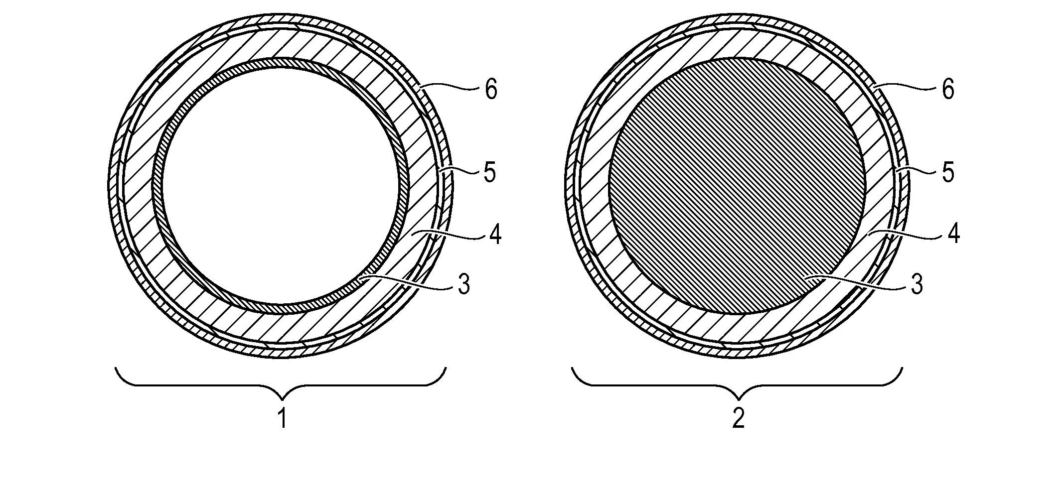
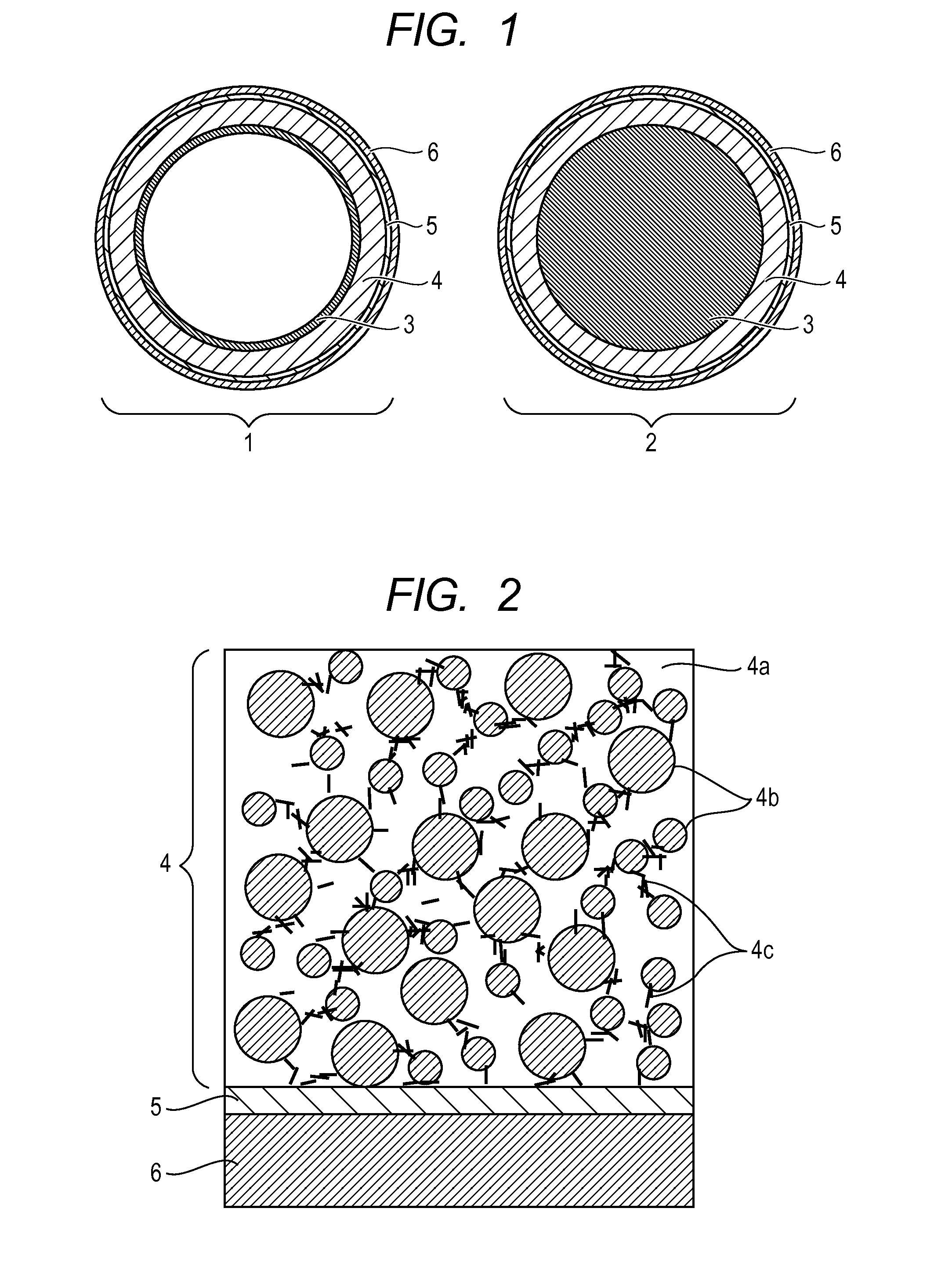
[0058]Then, the present invention is described by taking as an example a fixing member in which the substrate 3, the elastic layer 4, the adhesive layer 5 and the releasing layer 6 are stacked in this order. The surface of the releasing layer 6 is in contact with a member to be heated. Herein, a nickel-plated film is used as the substrate 3, a silicone rubber adhesive is used as the adhesive layer 5, and a tube made of a copolymer (PFA) of tetrafluoroethylene (TFE) and perfluoroalkyl vinyl ether (FVA) is used as the releasing layer 6. The thicknesses and the values of various physical properties of the substrate 3, the adhesive layer 5 and the releasing layer 6 are shown in Table 2 below.

TABLE 2Specificheat atThick-ThermalconstantThermalnessdiffusivityDensitypressureconductivity(μm)(mm2 / sec)(g / cm3)(J / g · K)(W / (m · K))Substrate 34022.758.90.44790.5Adhesive50.110.971.90.2layer 5Releasing100.122.170.960.24layer 6

[0059]Then, the thermal diffusion length (μ410) when an alternating-curren...

second embodiment

[0078]A fixing belt in which a nickel-plated film is used as the substrate 3, the silicone rubber elastic layer 4D used above is used as the elastic layer 4, the adhesive layer 5 is not provided, and the releasing layer 6 is directly formed by a fluororesin coating is taken as an example. The configurations and the values of physical properties of the respective layers are shown in Table 4 below.

TABLE 4Specificheat atThick-ThermalconstantThermalnessdiffusivityDensitypressureconductivity(μm)(mm2 / sec)(g / cm3)(J / g · K)(W / (m · K))Substrate 34022.758.900.4590.50Elastic3001.112.310.972.49layer 4DReleasing100.122.171.000.26layer 6

[0079]The fixing belt has a configuration corresponding to Example B-2.

[0080]The thermal diffusion length (μ410), when an alternating-current temperature wave having a frequency of 10 Hz is applied to the surface of the releasing layer of such the fixing belt, is calculated.

μ410=(0.12 / (π·f))0.5=61.8×10⁻³ mm=61.8 μm

Since the value is larger than a thickness (=10 μm)...

examples

[0235]Hereinafter, the present invention will be more specifically described using Examples.


PUM


Abstract

The present invention is directed to providing a fixing member that has a flexible surface and that can supply a larger amount of heat to a material to be recorded and a toner in a shorter period of time. The fixing member comprises a substrate, an elastic layer and a releasing layer, wherein thermal effusivity in a depth region from a surface of the releasing layer is 1.5 [kJ / (m2·K·sec0.5)] or more, the depth region corresponding to a thermal diffusion length when an alternating-current temperature wave having a frequency of 10 Hz is applied to the surface of the releasing layer, and a surface micro rubber hardness is 85 degrees or less.

Description

CROSS-REFERENCE TO RELATED APPLICATIONS[0001]This application is a continuation of International Application No. PCT / JP2013 / 007404, filed Dec. 17, 2013, which claims the benefit of Japanese Patent Application No. 2012-277247, filed Dec. 19, 2012 and Japanese Patent Application No. 2012-282972, filed Dec. 26, 2012.BACKGROUND OF THE INVENTION[0002]1. Field of the Invention[0003]The present invention relates to an electrophotographic fixing member. The present invention also relates to a fixing apparatus and an electrophotographic image forming apparatus using the member.[0004]2. Description of the Related Art[0005]In general, in a heat-fixing apparatus for use in an electrophotographic system such as a laser printer or a copier, rotation members such as a pair of a heated roller and a roller, a film and a roller, a belt and a roller, and a belt and a belt are in pressure-contact with each other.[0006]Then, a material to be recorded, which holds an image by an unfixed toner, is introdu...

Claims


Application Information

Patent Timeline
Patent Type & Authority Applications(United States)
IPC IPC(8): G03G15/20
CPCG03G15/2057G03G2215/2035
Inventor MATSUNAKA, KATSUHISAKISHINO, KAZUOTAKAHASHI, MASAAKIABE, KATSUYA
Owner CANON KK
Why Eureka
Try Eureka