Electrophotographic fixing member, fixing apparatus and electrophotographic image forming apparatus

a technology of electrophotographic image and fixing member, which is applied in the direction of electrographic process apparatus, instruments, optics, etc., can solve the problem of large amount of heat needed to allow the toner image to be sufficiently fixed, and achieve the effect of high thermal effusivity, stable high-definition image, and flexible surfa

Active Publication Date: 2015-06-23
CANON KK
View PDF20 Cites 10 Cited by
  • Summary
  • Abstract
  • Description
  • Claims
  • Application Information

AI Technical Summary

Benefits of technology

[0027]Meanwhile, not only the enhancement in ability to supply heat to a member to be heated but also the reduction in micro rubber hardness on the surface is demanded for the fixing member, as described above. The ability of the fixing member to supply heat to a member to be heated can be enhanced by increasing the content of a filler in the predetermined depth region from the surface of the fixing member, corresponding to the thermal diffusion length.
[0030]The present invention is also directed to providing a fixing apparatus that can favorably fix a toner on a recording medium even in a short dwell time, as well as an electrophotographic image forming apparatus.
[0035]According to the present invention, a fixing member that has high thermal effusivity in the vicinity of the surface thereof while the flexibility of the surface can be obtained. Further, according to the present invention, a fixing apparatus that can stably provide sufficient heat to a toner and a medium to be recorded while excessive pressure-contact of the toner is suppressed, can be obtained.
[0036]Furthermore, according to the present invention, an electrophotographic image forming apparatus that can stably provide a high-definition image can be obtained.

Problems solved by technology

In particular, in the case of a color image, unfixed toner images of multiple colors are present while being stacked in many layers, and thus a large amount of heat is needed for allowing the toner images to be sufficiently fixed.

Method used


Image

  • Electrophotographic fixing member, fixing apparatus and electrophotographic image forming apparatus
  • Electrophotographic fixing member, fixing apparatus and electrophotographic image forming apparatus
  • Electrophotographic fixing member, fixing apparatus and electrophotographic image forming apparatus

Examples


examples

[0244]Hereinafter, the present invention will be more specifically described using Examples.

example a-1

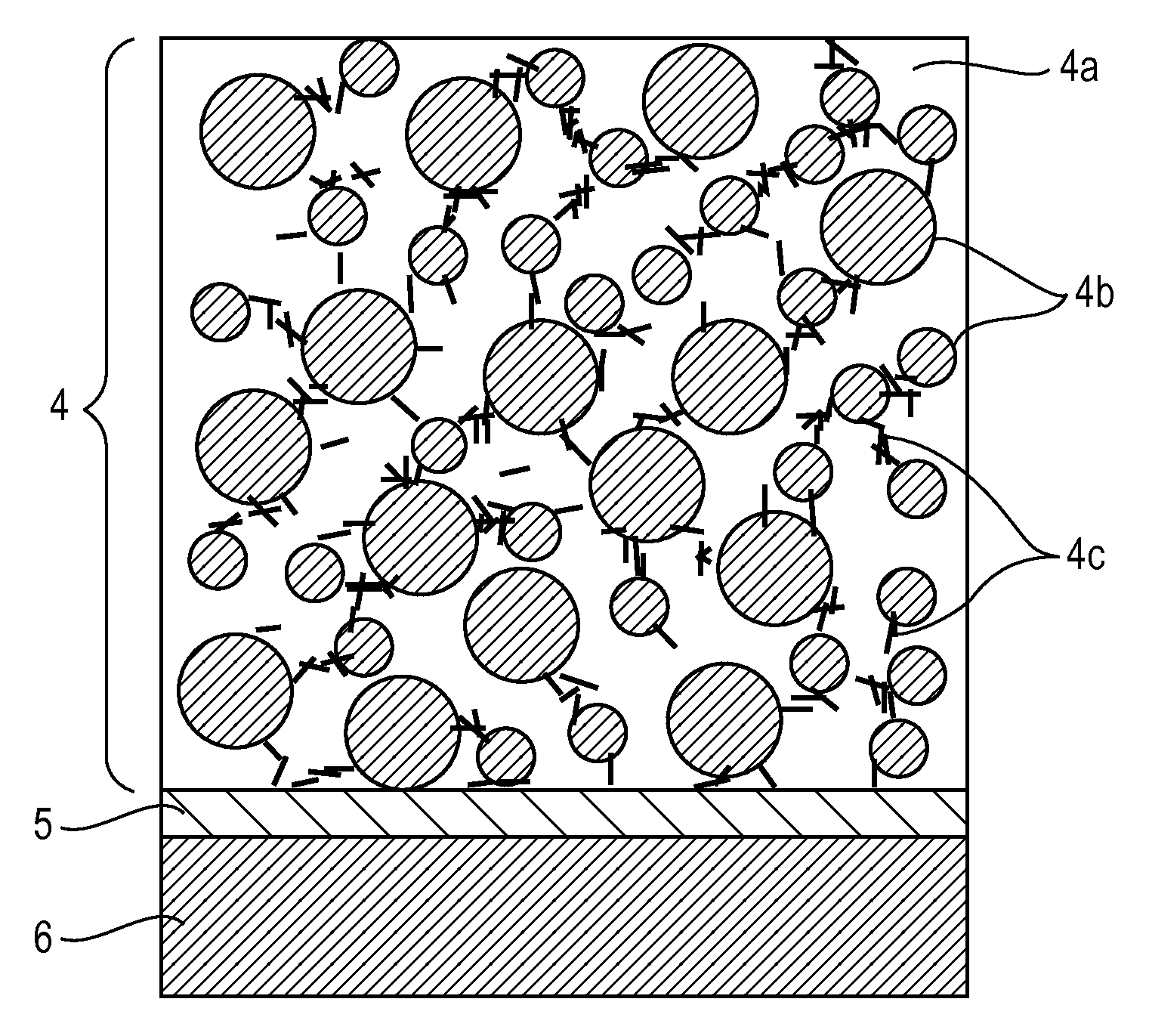
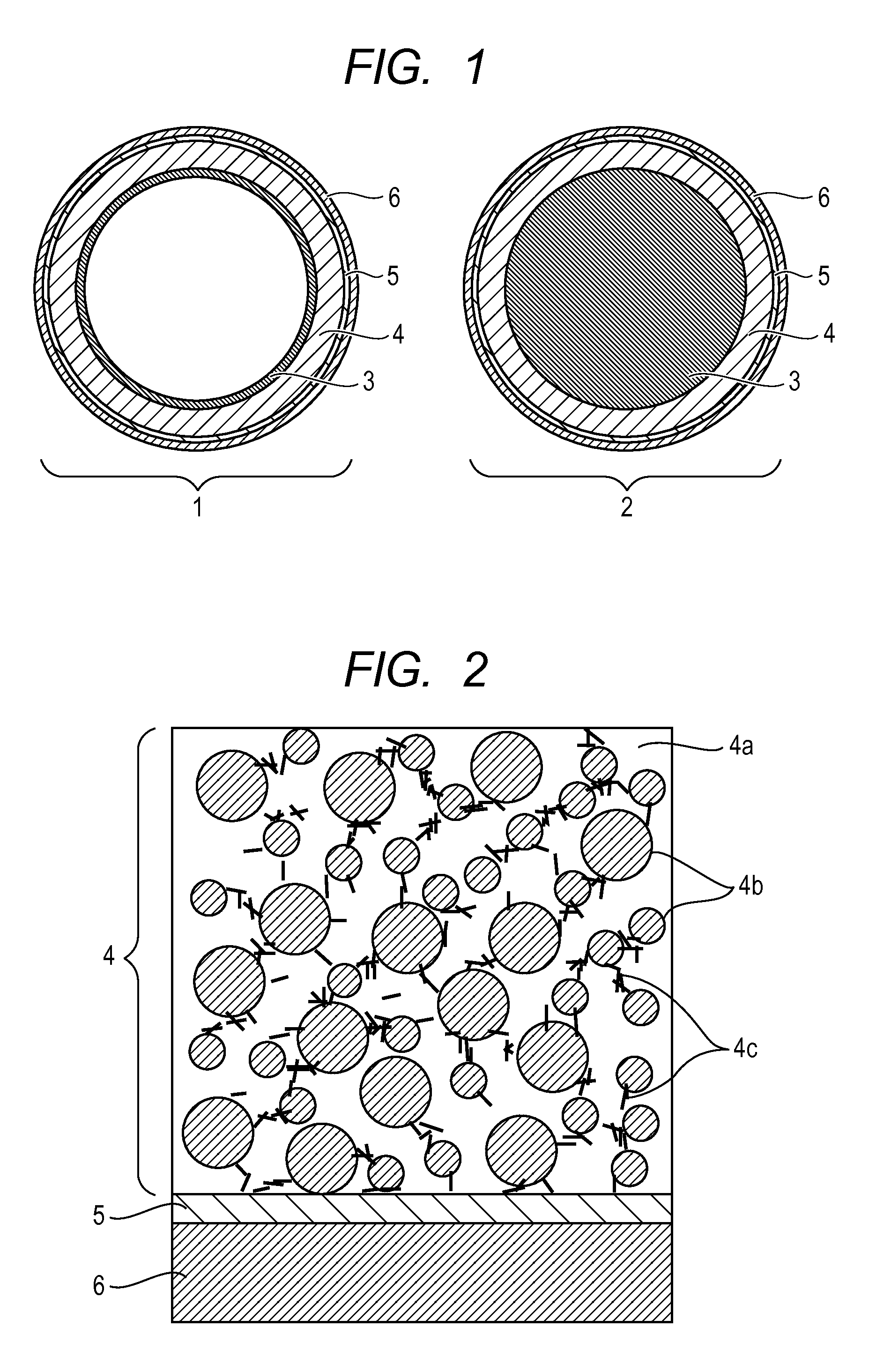
[0245]A high-purity truly spherical alumina (trade name: Alunabeads CB-A25BC; produced by Showa Titanium Co., Ltd.) as a filler was compounded with a commercially available addition-curing type silicone rubber stock solution (trade name: SE1886; “A-liquid” and “B-liquid” produced by Dow Corning Toray Co., Ltd. were mixed in equal amounts) in 35% by volume in a volume ratio based on a cured silicone rubber layer, and kneaded. Thereafter, vapor grown carbon fibers (trade name: carbon nanofiber • VGCF-S; produced by Showa Denko K. K.) as a filler were further added in 2% by volume in a volume ratio, and kneaded to provide a silicone rubber admixture.

[0246]Herein, the volume heat capacity (Cp·ρ) of each of the fillers is as follows. Each physical property value was measured in a room temperature environment of 25° C.

[0247]Alunabeads CB-A25BC: 3.03 [mJ / m3·K]

[0248]Carbon nanofiber • VGCF-S: 3.24 [mJ / m3·K]

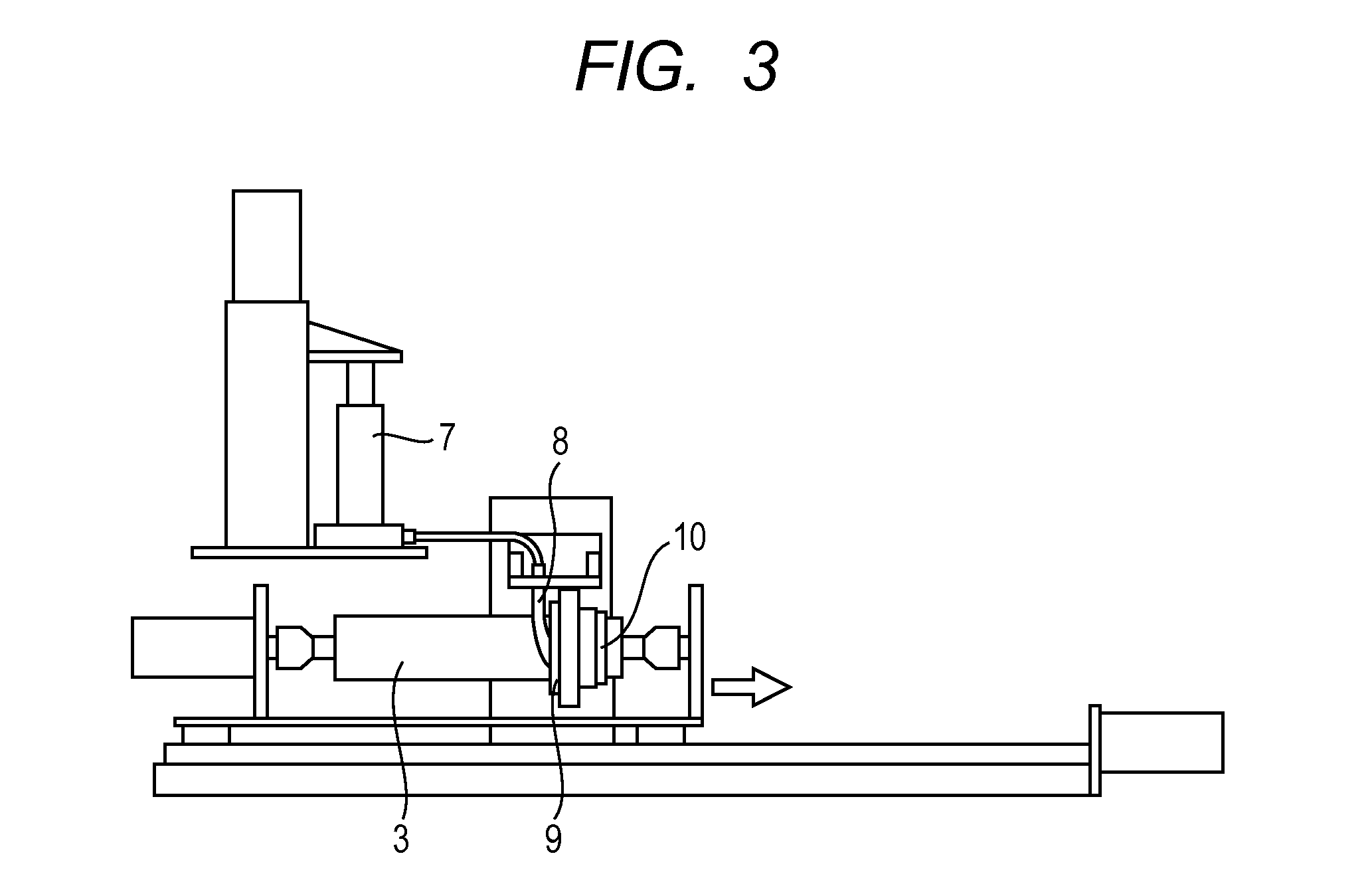
[0249]As a substrate, a nickel-plated, endless-shaped sleeve whose surface was subjec...

example a-11 , example a-15

Example A-11, Example A-15

zinc oxide (trade name: LPZINC-11; produced by Sakai Chemical Industry Co., Ltd.): 3.02 [mJ / m3·K];


PUM


Abstract

The present invention is directed to providing a fixing member that has a flexible surface and that can supply a larger amount of heat to a material to be recorded and a toner in a shorter period of time. The fixing member comprises a substrate, an elastic layer and a releasing layer, wherein thermal effusivity in a depth region from a surface of the releasing layer is 1.5 [kJ / (m2·K·sec0.5)] or more, the depth region corresponding to a thermal diffusion length when an alternating-current temperature wave having a frequency of 10 Hz is applied to the surface of the releasing layer, and a surface micro rubber hardness is 85 degrees or less.

Description

CROSS-REFERENCE TO RELATED APPLICATIONS[0001]This application is a continuation of International Application No. PCT / JP2013 / 007404, filed Dec. 17, 2013, which claims the benefit of Japanese Patent Application No. 2012-277247, filed Dec. 19, 2012 and Japanese Patent Application No. 2012-282972, filed Dec. 26, 2012.BACKGROUND OF THE INVENTION[0002]1. Field of the Invention[0003]The present invention relates to an electrophotographic fixing member. The present invention also relates to a fixing apparatus and an electrophotographic image forming apparatus using the member.[0004]2. Description of the Related Art[0005]In general, in a heat-fixing apparatus for use in an electrophotographic system such as a laser printer or a copier, rotation members such as a pair of a heated roller and a roller, a film and a roller, a belt and a roller, and a belt and a belt are in pressure-contact with each other.[0006]Then, a material to be recorded, which holds an image by an unfixed toner, is introdu...

Claims


Application Information

Patent Timeline
Patent Type & Authority Patents(United States)
IPC IPC(8): G03G15/20
CPCG03G15/2057G03G2215/2035
Inventor MATSUNAKA, KATSUHISAKISHINO, KAZUOTAKAHASHI, MASAAKIABE, KATSUYA
Owner CANON KK
Why Eureka
Try Eureka