Pressure relief device for swimming pools

a technology for swimming pools and pressure relief devices, which is applied in the direction of gyms, buildings, construction, etc., can solve the problems of swimming pool being destroyed, difficult to get it to go back to its original location, and the pool to be lifted out of the ground

Inactive Publication Date: 2014-09-18
STACHEL MICHAEL P +1
View PDF3 Cites 1 Cited by
  • Summary
  • Abstract
  • Description
  • Claims
  • Application Information

AI Technical Summary

Problems solved by technology

It has been known on several occasions, where there have been no spring activated water pressure relief devices or the mechanical pressure relief devices have not been removed, when the pool is empty and left unattended, that significant water pressure build up underneath the pool has caused the pool to lift out of the ground.
After the pool h

Method used


Image

  • Pressure relief device for swimming pools
  • Pressure relief device for swimming pools

Examples


Embodiment Construction

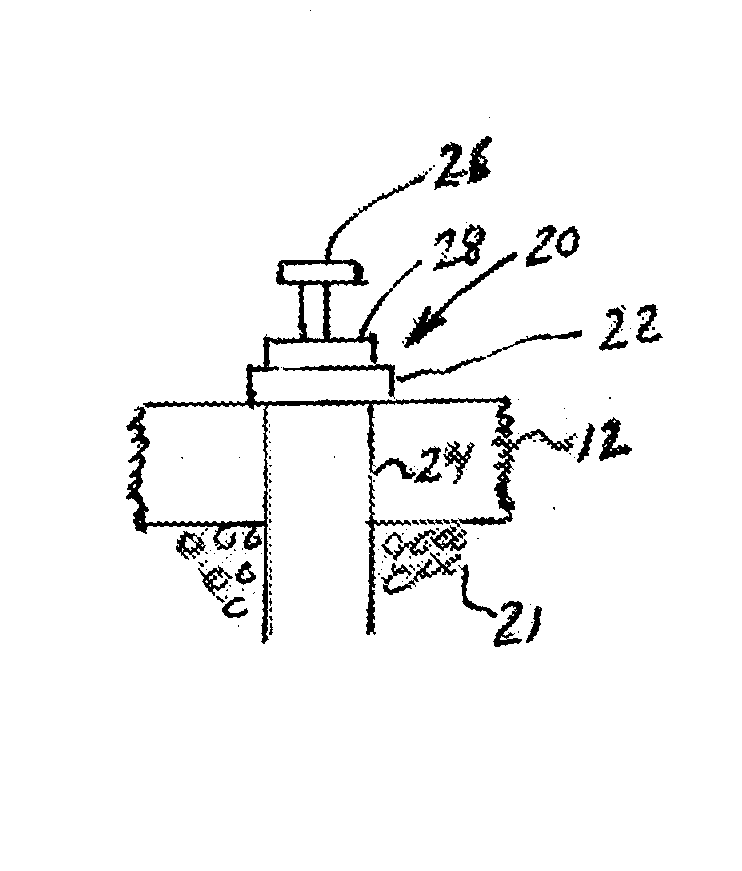
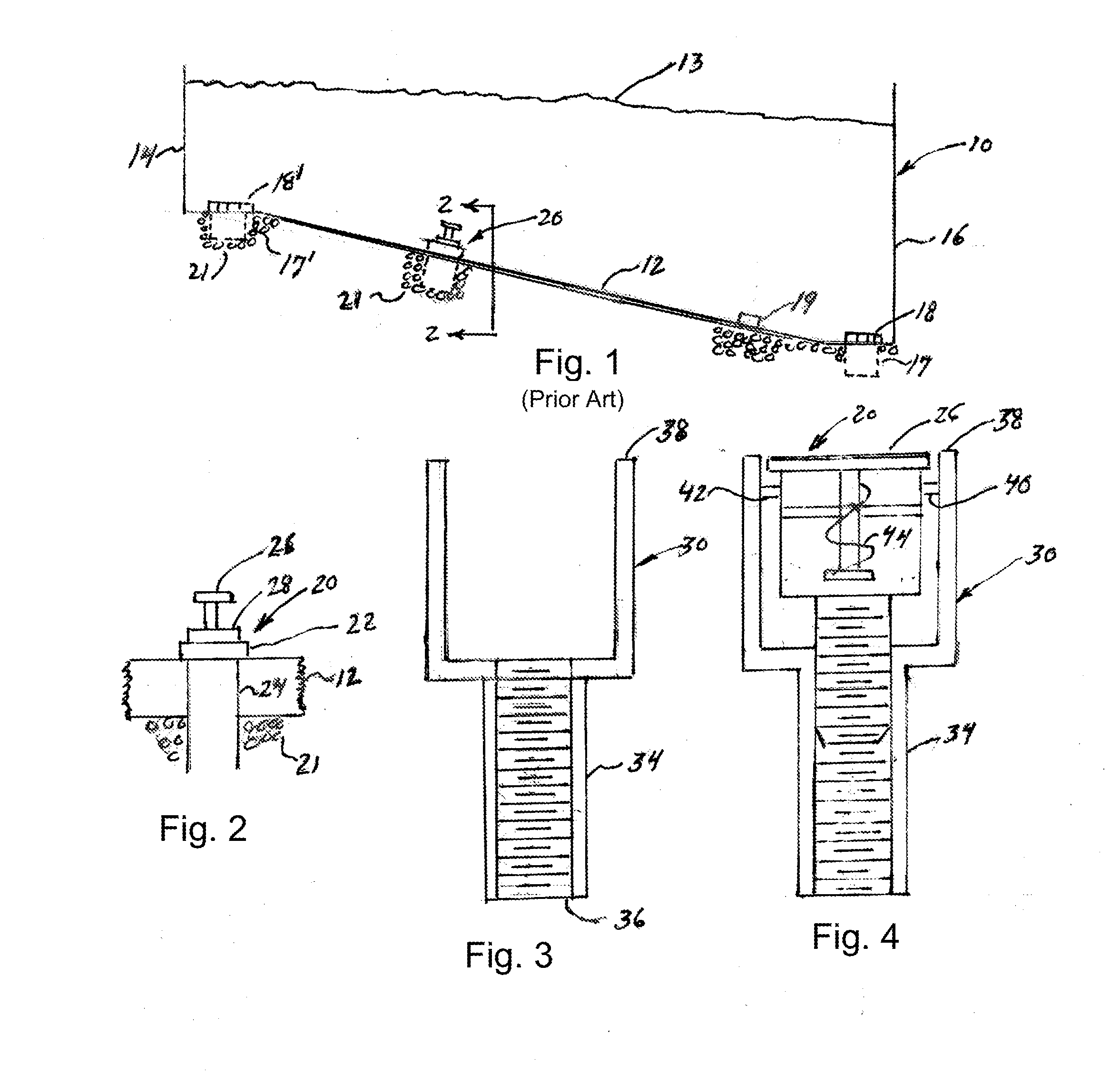
[0008]Referring to FIG. 1, a swimming pool 10 having a sloping bottom 12 is generally filled to a level shown by line 13. Conventional in-ground swimming pools made of poured or gunned concrete generally have a shallow end 14 and a deep end 16. In a conventional concrete pool the deep end 16 bottom contains a conventional water return fixture 17 for collecting pool water for recirculation through a water filtration system. Likewise, the shallow end 14 also contains an identical water return fixture 17′. Water return fixtures 17, 17′ are fitted with safety covers 18, 18′ as is well known in pool construction and user safety. The bottoms of fixtures 18,18′ are generally fitted with plugs (not shown) that can be removed when the pool is empty periodically for cleaning or painting. Removal of the plugs allows water accumulating under the pool to enter the pool for removal, thus preventing water pressure from building up under the pool.

[0009]In addition to pressure relief plugs in fixtur...


PUM


Abstract

Pressure relief assembly for a swimming pool that presents a smooth surface to the upper surface of the bottom of the pool when the valve is in a closed position.

Description

BACKGROUND OF THE INVENTION[0001]It is known that in-ground swimming pools are built with pressure relief plugs placed at strategic locations in the bottom of the pool. The pressure relief plugs can either be spring activated or mechanically removed when the swimming pool is emptied of water. The pressure relief devices are required so that water pressure building up underneath an empty swimming pool can be forced into the pool and thus removed conveniently. It has been known on several occasions, where there have been no spring activated water pressure relief devices or the mechanical pressure relief devices have not been removed, when the pool is empty and left unattended, that significant water pressure build up underneath the pool has caused the pool to lift out of the ground. After the pool has lifted out of the ground, it is very difficult to get it to go back to its original location. Point of fact, most of the time the swimming pool has to be destroyed and a new pool put in ...

Claims


Application Information

Patent Timeline
IPC IPC(8): E04H4/14
CPCE04H4/14E04H4/0075
Inventor STACHEL, MICHAEL P.STACHEL, JR., MICHAEL P.
Owner STACHEL MICHAEL P
Why Eureka
Try Eureka