
View rendering for the provision of virtual eye contact using special geometric constraints in combination with eye-tracking

a technology of geometric constraints and virtual eye contact, applied in the field of new support for video communication with the provision of eye contact, can solve the problems of lack of eye contact, “static” or unnatural appearance of the local participant,

Active Publication Date: 2014-09-18
FRAUNHOFER GESELLSCHAFT ZUR FOERDERUNG DER ANGEWANDTEN FORSCHUNG EV
View PDF8 Cites 41 Cited by
  • Summary
  • Abstract
  • Description
  • Claims
  • Application Information

AI Technical Summary

Benefits of technology

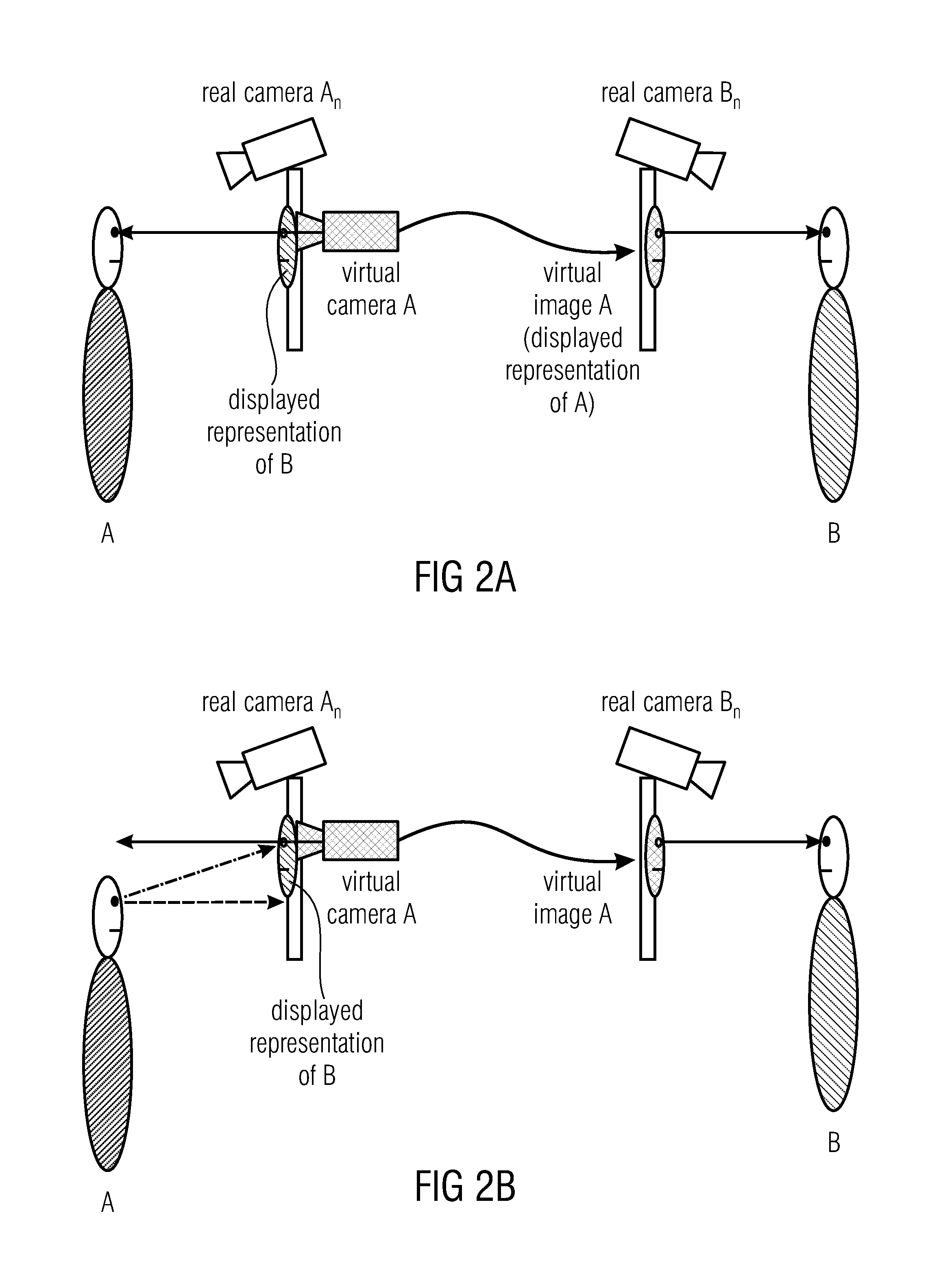
The embodiments and methods described in this patent make it possible to determine the position and orientation of a virtual camera based on the display position of a remote participant and the position of a local participant in a video communication system. This allows the virtual camera to transmit an image or sequence of images to the remote participant in a way that gives the impression that they are viewing the system from the perspective of the local participant. The system can also analyze the inbound image or images to identify specific image features and determine their location within the image. This information can be used to create a virtual view that shows the local participant from the perspective of the virtual camera. The technical effects of this invention include improved virtual camera positioning and a more immersive video communication experience.

Problems solved by technology

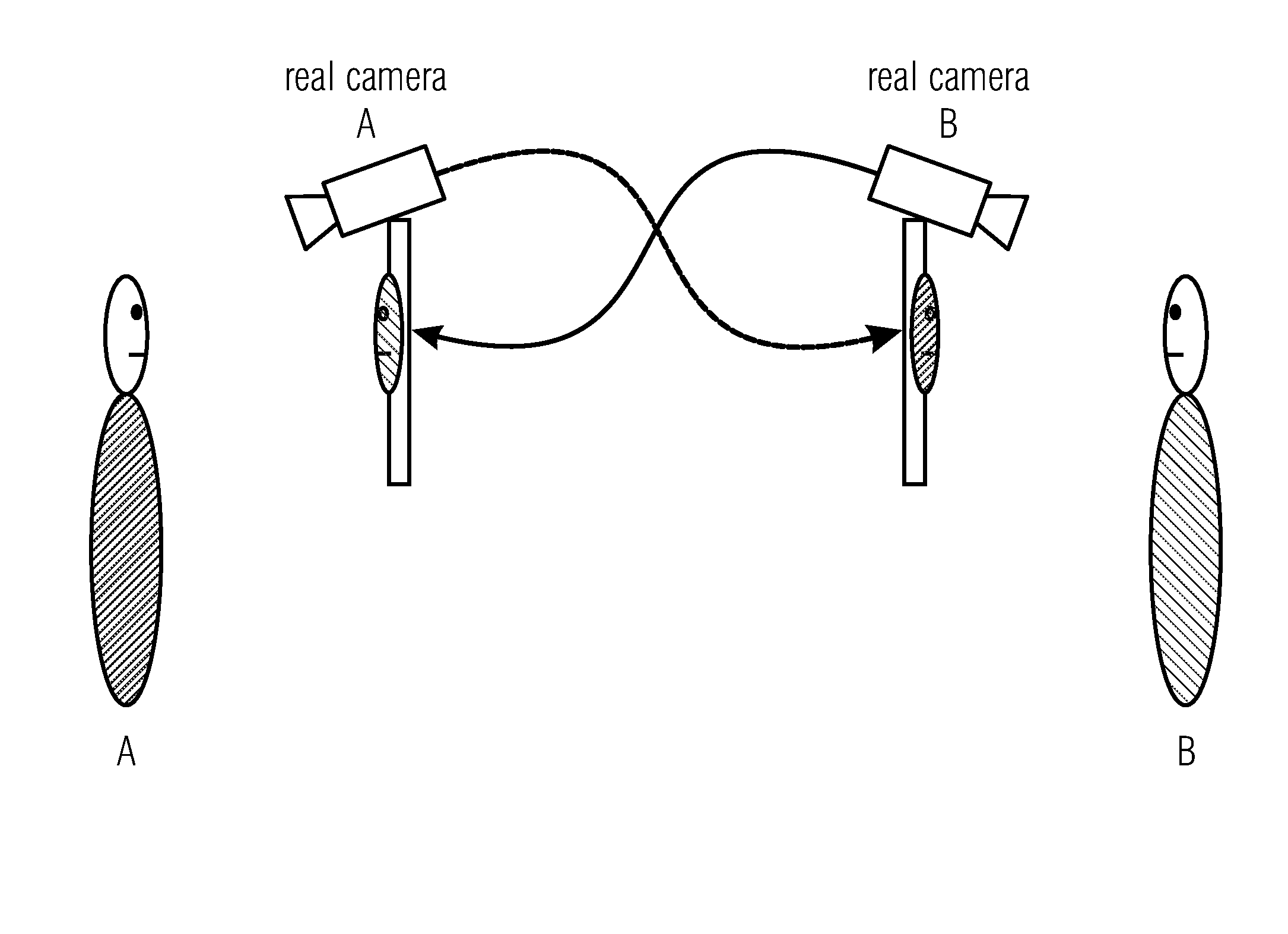
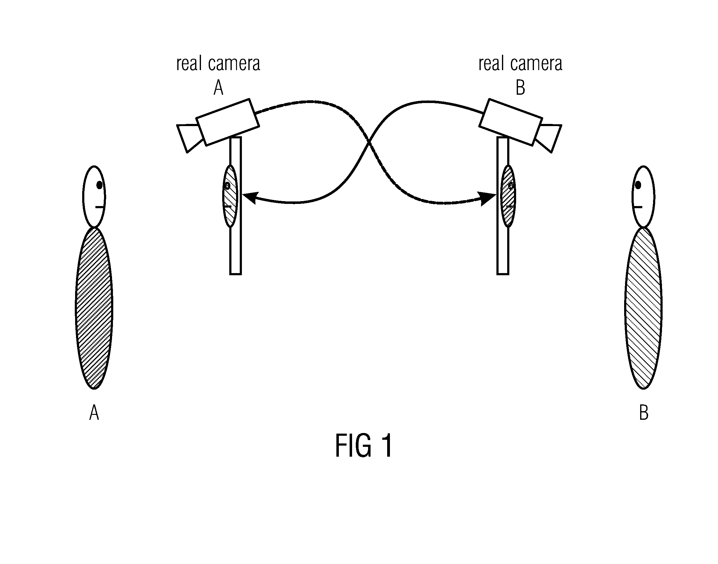
A significant drawback of current video communication systems is the lack of eye contact.
This may result in a “static” or unnatural appearance of the local participant when being rendered at the remote site.
However, in U.S. Pat. No. 7,532,230 B1, the creation of the correct virtual view is not based on the concept of a virtual camera.

Method used


Image

  • View rendering for the provision of virtual eye contact using special geometric constraints in combination with eye-tracking
  • View rendering for the provision of virtual eye contact using special geometric constraints in combination with eye-tracking
  • View rendering for the provision of virtual eye contact using special geometric constraints in combination with eye-tracking

Examples


Embodiment Construction

[0020]In order to overcome the problem of the lack of eye contact, some video communication systems generate a novel view of the remote participants based on a virtual camera, which is placed at the position where the users are looking at on the display.

[0021]The provision of virtual eye-contact typically necessitates exact rendering of virtual views in critical face regions, like eyes and nose that are very sensitive due to psycho-visual reasons. Apart from precise depth information in these regions, rendering has to respect special geometrical constraints referring to the line of sight. According to an aspect of the present invention, these constraints are addressed by special rendering methods in combination with an eye tracker. In other words, a new approach to support video communication with the provision of eye contact is described. The new approach of one or more aspects of the present invention is based on 3D analysis of the local and remote participant, estimating the view...


PUM


Abstract

A virtual camera pose determiner is configured to determine a position and an orientation of a virtual camera. The position of the virtual camera is determined on the basis of a display position of a displayed representation of a remote participant on a display. The orientation of the virtual camera is determined on the basis of a geometrical relation between the display position of the remote participant on the display, and a position of a local participant. The virtual camera is configured to transmit an image or a sequence of images to the remote participant, so that an image provided by the virtual camera has the view on the local participant as is if viewed from the display position. Further embodiments provide a video communication system having a virtual camera pose determiner for providing a virtual camera pose on basis of the display position and the position of the local participant.

Description

CROSS-REFERENCE TO RELATED APPLICATIONS[0001]This application is a continuation of copending International Application No. PCT / EP2012 / 073985, filed Nov. 29, 2012, which is incorporated herein by reference in its entirety, and additionally claims priority from U.S. Provisional Application No. 61 / 564,915, filed Nov. 30, 2011, which is also incorporated herein by reference in its entirety.BACKGROUND OF THE INVENTION[0002]Embodiments of the present invention relate to a new approach to support video communication with the provision of eye contact. Some embodiments relate to a virtual camera pose determiner. Some embodiments relate to a video communication system. Some embodiments relate to a method for determining a position and an orientation of a virtual camera. Some embodiments relate to a method for video communication.[0003]A significant drawback of current video communication systems is the lack of eye contact. This is caused due to fact that the user is looking onto the screen to...

Claims


Application Information

Patent Timeline
Patent Type & Authority Applications(United States)
IPC IPC(8): H04N7/14
CPCH04N7/144
Inventor ATZPADIN, NICOLEFELDMANN, INGOKAUFF, PETERSCHREER, OLIVERWAIZENEGGER, WOLFGANG
Owner FRAUNHOFER GESELLSCHAFT ZUR FOERDERUNG DER ANGEWANDTEN FORSCHUNG EV
Learn More