Display control apparatus, display control method, camera system, control method for camera system, and storage medium

Active Publication Date: 2014-09-18
CANON KK
View PDF4 Cites 8 Cited by
  • Summary
  • Abstract
  • Description
  • Claims
  • Application Information

AI Technical Summary

Benefits of technology

The present invention provides a display control apparatus that can detect an event and display a predetermined image related to the event together with a video of the event. This allows for quicker response and better visual representation of the event.

Problems solved by technology

However, in conventional monitoring systems, during display of a video captured by a certain camera that is currently selected, if detection such as passage detection and intrusion detection is performed by the selected camera, such detection can be displayed on a screen together with a passage line on which passage was detected and a region in which intrusion was detected; however, if such detection is performed by another camera, such detection cannot be displayed on the screen.
This gives rise to the possibility that a detected event is overlooked, and even if the occurrence of the detection is acknowledged, it is not possible to specifically check where the site of the detection is on a video.

Method used


Image

  • Display control apparatus, display control method, camera system, control method for camera system, and storage medium
  • Display control apparatus, display control method, camera system, control method for camera system, and storage medium
  • Display control apparatus, display control method, camera system, control method for camera system, and storage medium

Examples


first embodiment

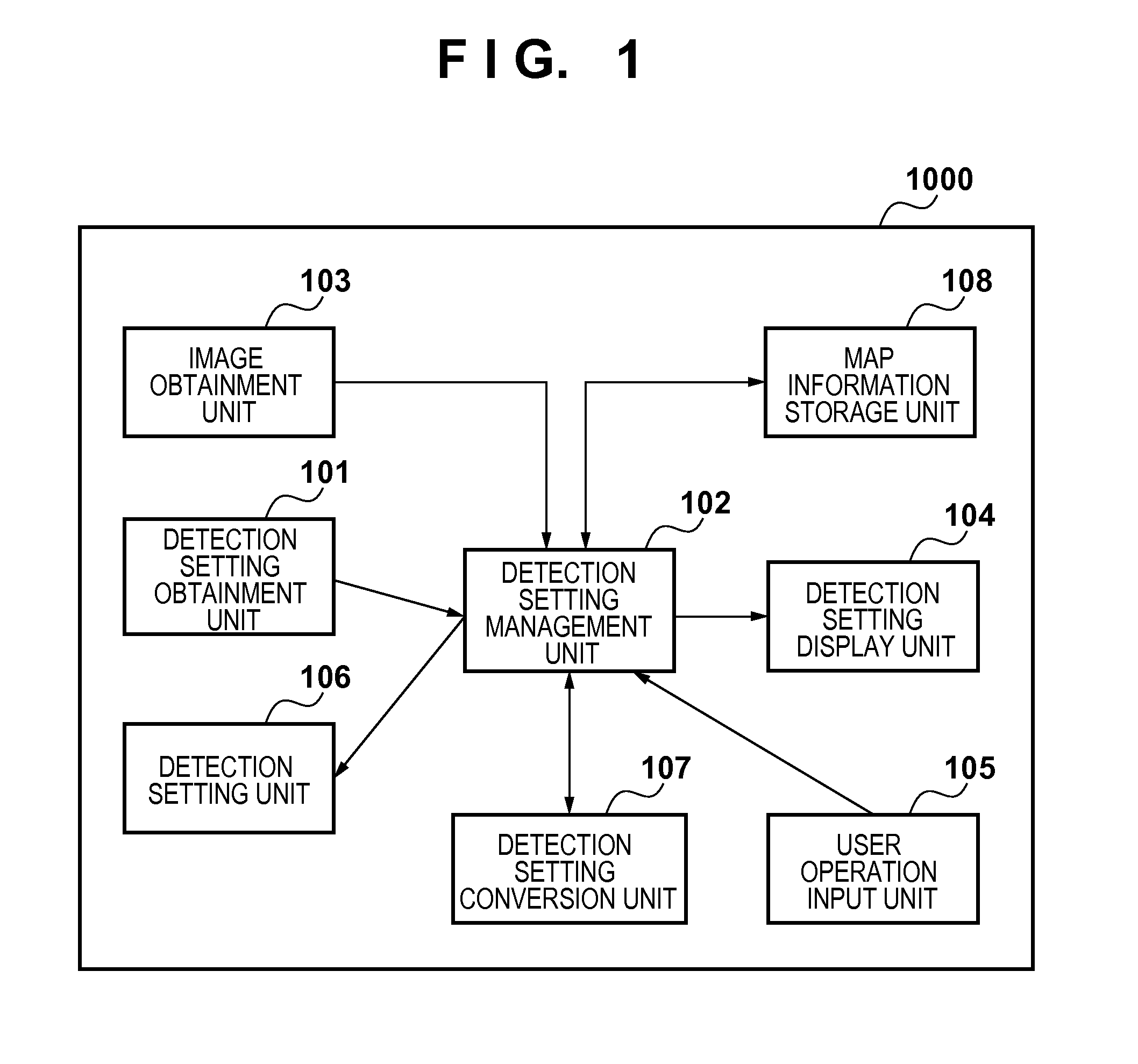
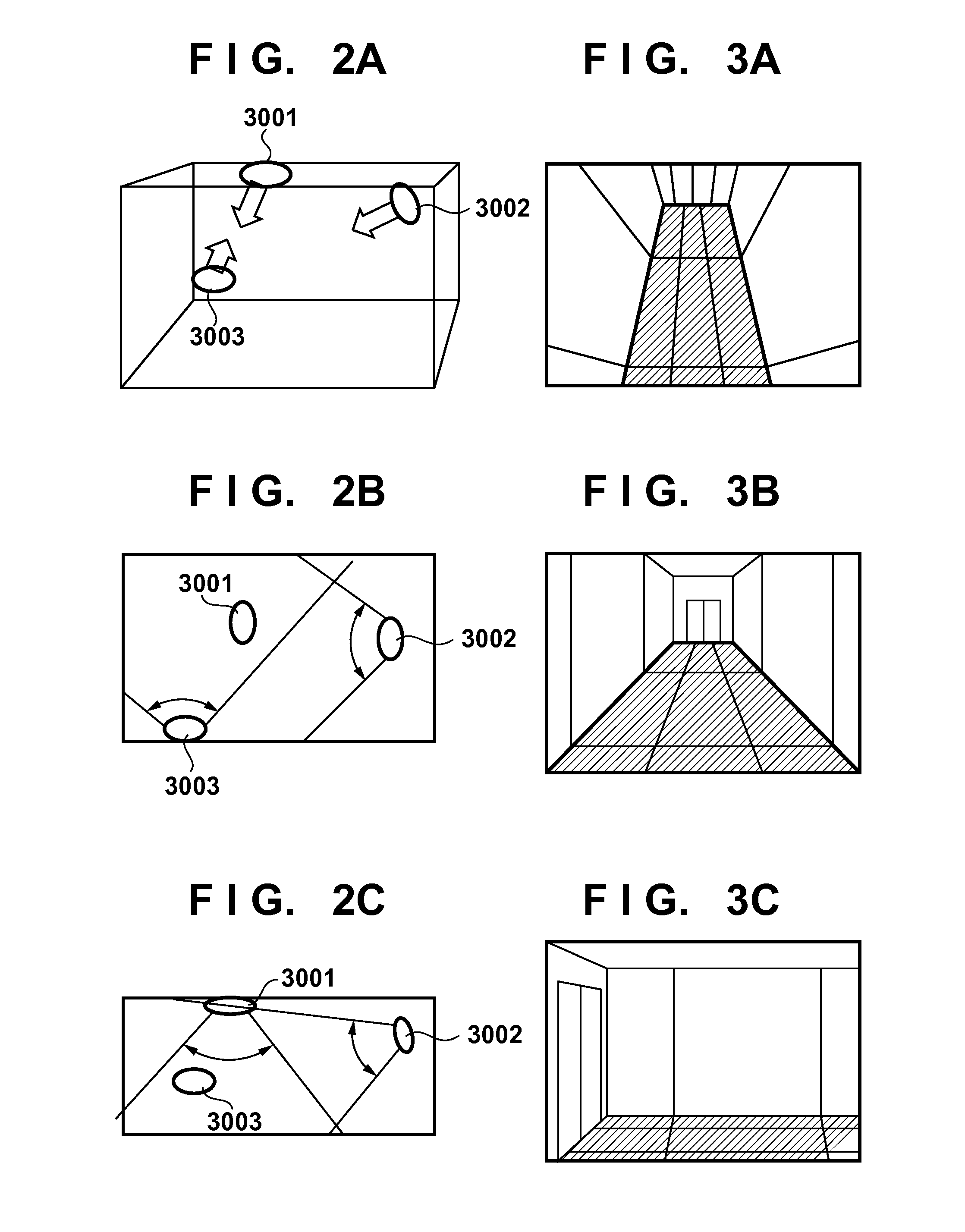
[0026]FIG. 7 shows an example of a configuration of a monitoring system according to the present embodiment. The monitoring system includes a detection setting terminal 1000, monitoring cameras 3001 to 3003, a monitoring video recording server 4000, and a detection notification display terminal 5000, which are connected via a network such as a LAN (local area network) 2000.

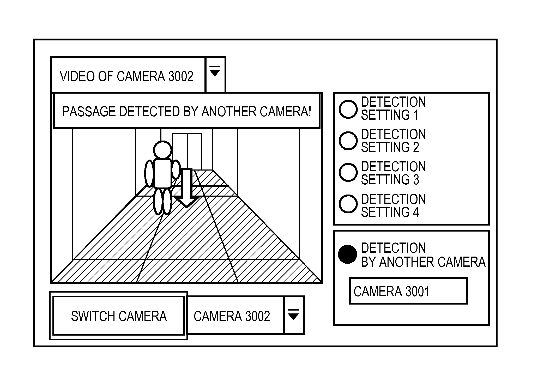
[0027]The detection setting terminal 1000 configures various types of detection settings, such as setting related to moving object detection functions of monitoring cameras, setting of a type of detection performed by the monitoring cameras (passage detection, intrusion detection, and the like), setting of a detection line segment for detecting passage in the case of passage detection, and setting of a closed region for detecting intrusion in the case of intrusion detection. A user configures detection settings via a touchscreen operation while viewing a capture screen displayed on the detection setting terminal 1...

second embodiment

[0089]In the first embodiment, regions captured by a plurality of cameras overlap one another, and detection settings are configured with respect to the overlapping regions. However, the present invention is not limited in this way. For example, in the case where cameras are installed in similar positions on different but identically-designed floors of an office building such that each camera detects passage of people who come in and out of a door, the identical design allows mapping on the same planar map, and therefore the present invention can be applied.

[0090]Furthermore, while detection settings are configured for the second camera continuously after the configuration of detection settings for the first camera in the first embodiment, a time interval may be set between the initial configuration of detection settings for the first camera and the configuration of detection settings for the next camera. In this case, if information of the first camera for which detection settings ...


PUM


Abstract

A display control apparatus comprising: a reception unit configured to receive a detection notification indicating detection of an event by a first camera; an image obtainment unit configured to obtain a video from a second camera; and a display control unit configured to, in a case where the detection notification is received from the first camera that corresponds to detection of the event in which an occurrence position is included in the video from the second camera, display a predetermined image corresponding to the detection of the event together with the video from the second camera.

Description

BACKGROUND OF THE INVENTION[0001]1. Field of the Invention[0002]The present invention relates to a display control apparatus that displays a video captured by a monitoring camera, a display control method, a camera system, a control method for a camera system, and a storage medium.[0003]2. Description of the Related Art[0004]In the field of monitoring systems, a technique to detect a moving object in a video using a video analysis technique is known. Furthermore, a technique to enable constant capturing and recognition of a detected moving object is known as a moving object tracking technique.[0005]Using the foregoing techniques, Japanese Patent Laid-Open No. 2002-374522 discloses a monitored region setting method for setting regions monitored by a plurality of installed monitoring cameras while checking videos of the monitoring cameras.[0006]However, in conventional monitoring systems, during display of a video captured by a certain camera that is currently selected, if detection s...

Claims


Application Information

Patent Timeline
IPC IPC(8): H04N7/18
CPCH04N7/181H04N7/188G08B13/19645G06V20/53
Inventor KITAGAWA, EIICHIRO
Owner CANON KK
Why Eureka
Try Eureka