Systems and methods for detecting and determining sources of power disturbances in connection with effective remediation

a technology of power disturbance and detection method, applied in the direction of electrical equipment, emergency protective arrangement details, electrical apparatus, etc., can solve the problems of increased voltage drop, increased voltage drop, and increased voltage drop

Active Publication Date: 2014-09-18
I EWM ACQUISITION LLC
View PDF2 Cites 54 Cited by
  • Summary
  • Abstract
  • Description
  • Claims
  • Application Information

AI Technical Summary

Benefits of technology

[0016]In one embodiment, the operational state of an electrical load device is determined by use of a current sensing or measuring device that monitors the current draw of the electric load. In one embodiment, the PPD may relax the disturbance detection parameters or inhibit remediation according to predetermined load state to ensure that the load maintains proper functionality. In another embodiment, the PPD may remediate a power disturbance according to a load state and / or line voltage condition. Further and according to another aspect, the PPD may remediate a power disturbance according to a load current anomaly and / or line voltage conditions. In further embodiments, aspects of the PPD generally enable the system to determine whether the source of the voltage disturbance is due to load operations or if the source of the voltage disturbance is from the power grid. Generally, the source of a voltage disturbance will dictate the execution and / or inhibition of remediation.

Problems solved by technology

Voltage sags on the power grid may occur when short circuits occur somewhere on the grid, a large load is connected to the grid, a sudden load change, etc.
While voltage sag correction is one method of addressing power disturbances having certain properties, such voltage sag correctors may not be suitable for many industrial applications.
There are multiple causes for a branch circuit-based voltage sag, such as incorrect feeder wire size, wherein the improper wire impedance being inserted into the circuit can cause a greater than necessary voltage drop.
However, some of the remediation techniques do not incorporate the working state of the load device into consideration prior to remediation of the voltage disturbance.
Furthermore, if the electrical load is causing a branch circuit-based sag, additional current limitation is not necessary as it further starves the electrical load of needed voltage, which may cause an unintentional nuisance trip.
Grid-based voltage sags have a tendency to starve electrical loads of voltage, which generally discharges the internal capacitance of the load device.
This single impedance may not contain the most appropriate value to limit the amount of current drawn due to the nature of the particular power disturbance occurrence.
This reduction in voltage can sometimes cause the connected electrical load to unintentionally turn off (e.g., nuisance trip) due to the voltage presented to the electrical load to drop below the required level for operation.
An unintentional loss of power to critical load systems may potentially be severely damaging and costly to operations.

Method used


Image

  • Systems and methods for detecting and determining sources of power disturbances in connection with effective remediation
  • Systems and methods for detecting and determining sources of power disturbances in connection with effective remediation
  • Systems and methods for detecting and determining sources of power disturbances in connection with effective remediation

Examples


discussion examples

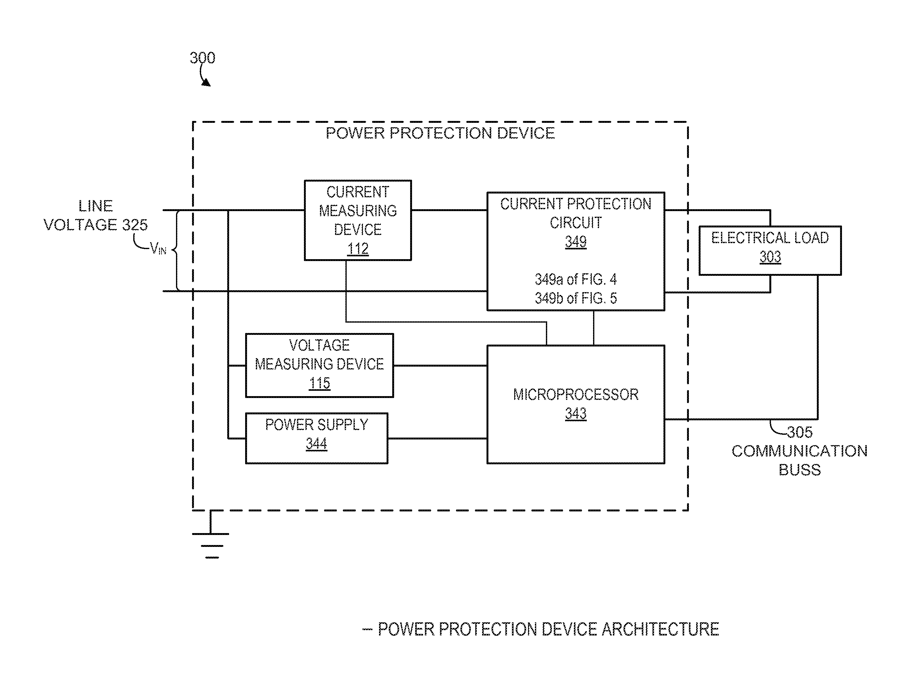
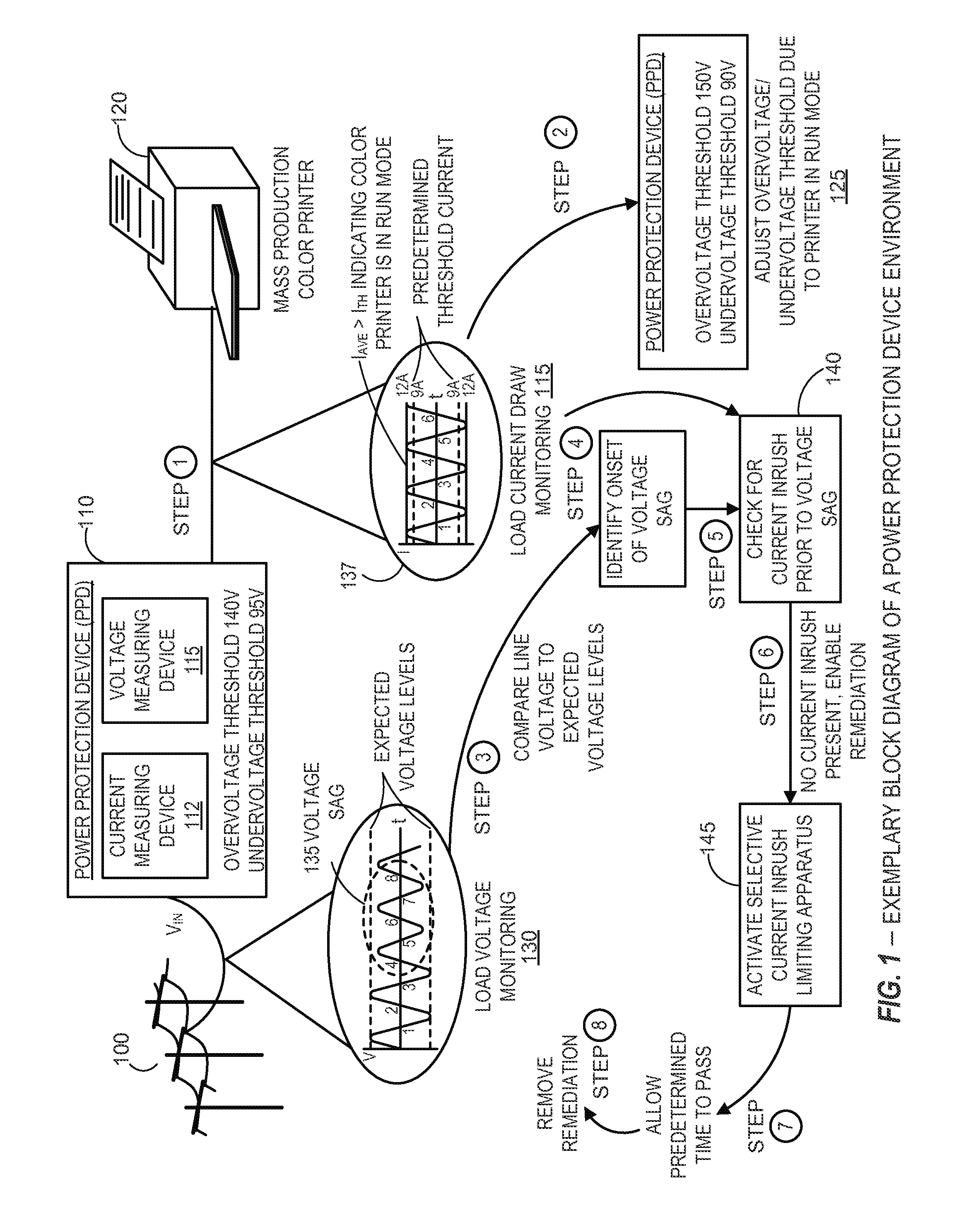
[0124]FIGS. 8 and 9 further illustrate alternate scenarios and embodiments involving the determination of an operative state of an exemplary load (e.g., a mass production color printer 120 and / or a soda machine 1010) corresponding to a power disturbance source identification and appropriate related remediation of the associated power disturbance. According to certain embodiments and as previously discussed, the power protection device (PPD) 110 generally comprises various mechanisms to remediate predetermined power disturbances, inhibit remediation according to predetermined parameters, and / or adjust various thresholds to protect operation of critical equipment.

[0125]As previously described, the scenario in connection with FIG. 1 described detection of a power disturbance, identifying the source of the power disturbance was the power grid, and remediating the power disturbance from the power grid. The scenario depicted in FIG. 8 differs from the scenario depicted in FIG. 1 such that...


PUM


Abstract

Apparatus and methods for selective protection of an electrical load from disturbances on an input power line. A power protection circuit includes a selectively variable inrush current limiting circuit and a switch for disconnecting the input power line from the load. A control circuit determines that the electrical load is in a first operational state, such as a standby mode or normal operation, or a second operational state, such as full operation at rated current. The power protection circuit provides variable inrush current limiting to the electrical load in response to a first category of disturbances when the electrical load is in the first operational state. The power protection circuit inhibits disconnecting the electrical load in response to a second category of disturbances when the electrical load is in the second operational state. Species of selectively variable current limiting circuits are also described.

Description

CROSS REFERENCE TO RELATED APPLICATION[0001]This application claims benefit under 35 U.S.C. §119(e) of U.S. Provisional Patent Application No. 61 / 783,567, filed Mar. 14, 2013, and entitled “Systems and Methods for Selective Current Limiting and Voltage Sag Discrimination”, which is incorporated herein by reference as if set forth herein in its entirety.TECHNICAL FIELD[0002]The present systems and methods relate generally to detection of power disturbances and appropriate remediation, and more particularly to the determination of power disturbances due to a load on a branch circuit or a power grid anomaly. Further, the present systems and methods relate generally to selective power disturbance remediation due to voltage and current parameters.BACKGROUND[0003]Power disturbances on a power grid system are not limited solely to lighting-induced voltage surges as previously thought. Voltage disturbances on power grid systems may embody other common forms such as voltage sags, momentary i...

Claims


Application Information

Patent Timeline
Patent Type & Authority Applications(United States)
IPC IPC(8): H02H9/02H02H3/10H02H3/20
CPCH02H9/02H02H3/207H02H3/10H02H1/043
Inventor LUCIANI, VINCENT P.BRIGHT, EUGENE
Owner I EWM ACQUISITION LLC
Why Eureka
Try Eureka