Decoupling Synchrophasor Based Control System for Multiple Distributed Energy Resources

a control system and energy resource technology, applied in the field of electric power grids, to achieve the effect of reducing power grid disturbance, and increasing the performance of the control system

Active Publication Date: 2017-11-30
PXISE ENERGY SOLUTIONS LLC
View PDF0 Cites 10 Cited by
  • Summary
  • Abstract
  • Description
  • Claims
  • Application Information

AI Technical Summary

Benefits of technology

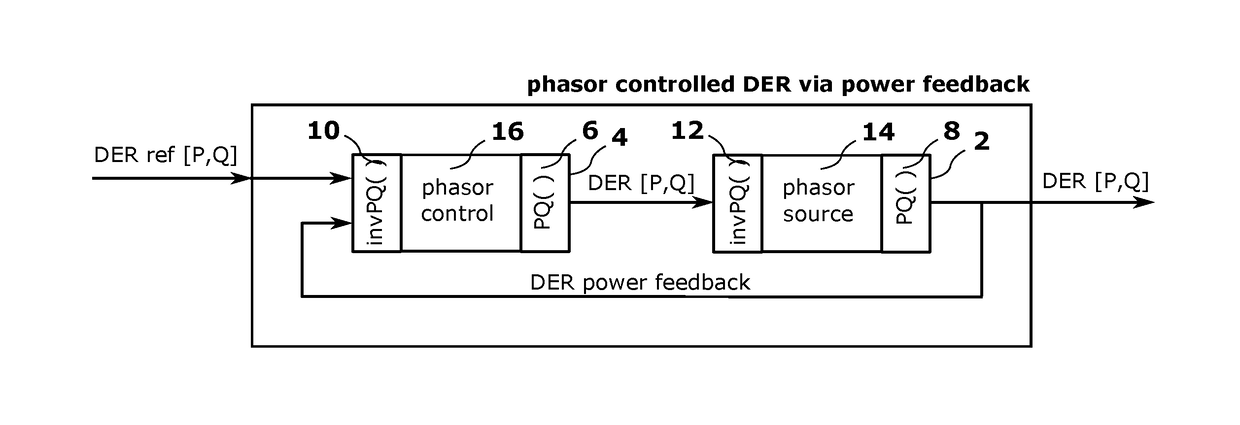
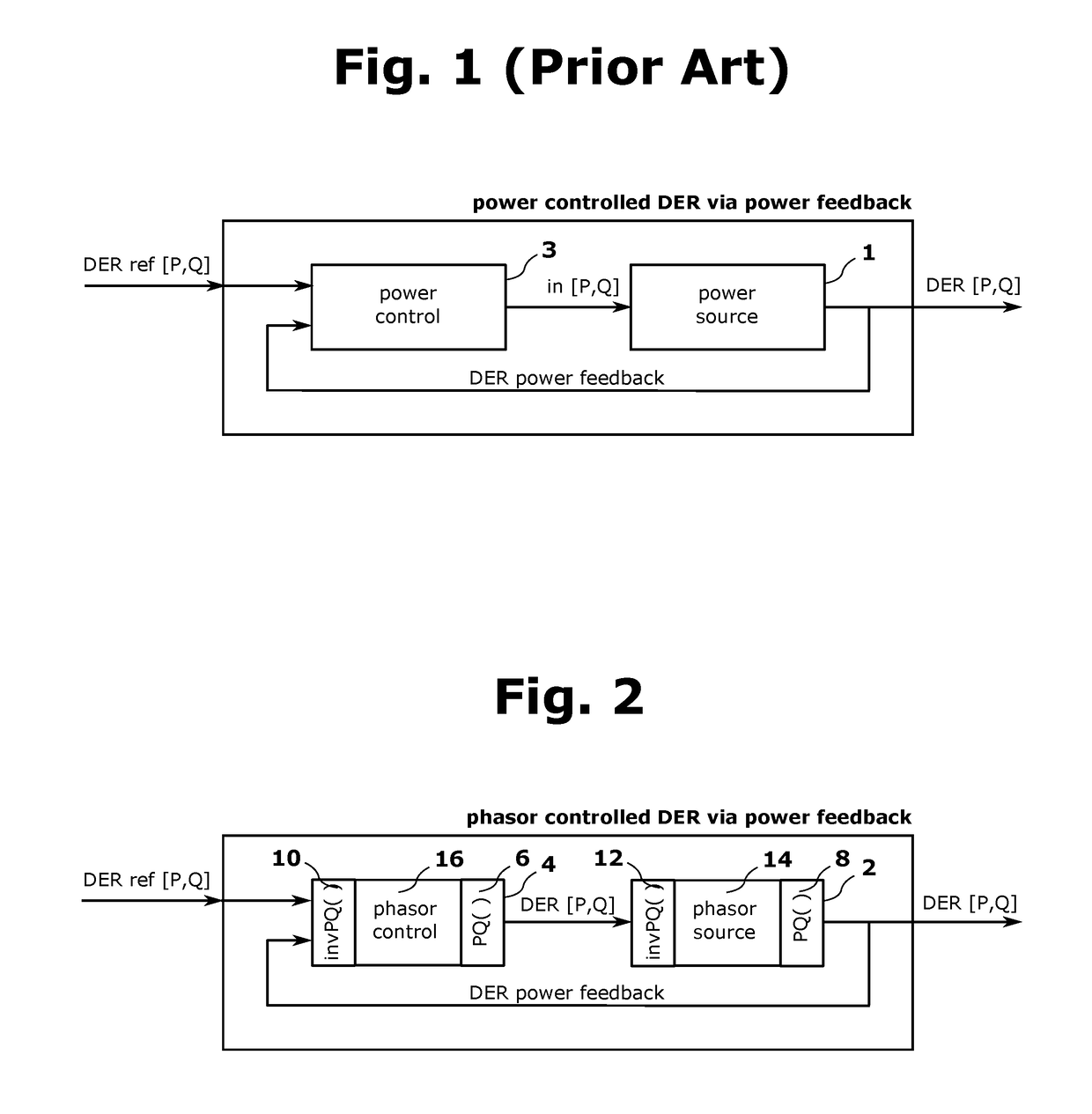
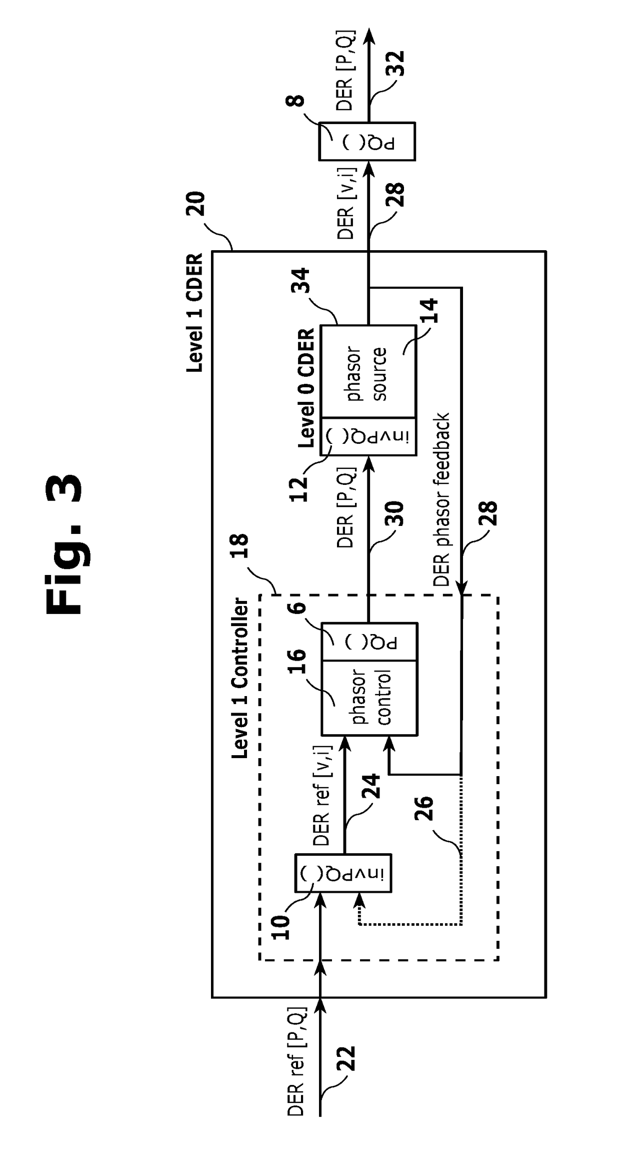
[0011]In one aspect, the invention uses time synchronized real and reactive power measurements in a high-speed feedback control system designed to mitigate disturbances while regulating the system to a specified real and reactive power setpoints. It also includes a control system that controls the state or the power of the system using the same controller structure. It incorporates a separate proportional integral combined with a derivative filter to mitigate power grid disturbances and also an output filter to adjust the output signal according to the response characteristics of the DERs. The invention provides an increase in the performance of the control system by using decoupled time synchronous input and output measurements. It uses either the decoupled pair (voltage magnitude and voltage angle) or the decoupled pair (current magnitude and power angle) as measured variables to precisely control real and reactive power while operating at high rates. This control structure can be reversed to form a decoupled control system regulating the pair (real power and reactive power) to obtain decoupled phasor output setpoints pairs for either (current magnitude and power angle) or (voltage magnitude and voltage angle.) These identically structured controllers can be used in cascade mode to directly control the power demand of the DER.

Problems solved by technology

These filters are extensively used in the controller such that the internal functionality of the controller has a limited number of independent control system objects.

Method used


Image

  • Decoupling Synchrophasor Based Control System for Multiple Distributed Energy Resources
  • Decoupling Synchrophasor Based Control System for Multiple Distributed Energy Resources
  • Decoupling Synchrophasor Based Control System for Multiple Distributed Energy Resources

Examples


Embodiment Construction

Nomenclature and Abbreviations

[0025]V—voltage amplitude measured in volt

β—unwrapped voltage phase angle, measured in radians

v—voltage phasor consisting of (V,β) pair

f—power frequency

I—current amplitude measured in ampere

γ—unwrapped current phase angle measured in radians

i—current phasor consisting of (I,γ) pair

α—power angle and defined as difference between β and γ

Ip—current power phasor Ip=Iejα

Ic=real part of current power phasor

Is—imaginary part of current power phasor

VA—Voltage Ampere

[0026]P—real power, measured in Watt.

Q—reactive power, measured in VA

S—apparent power (complex number S=P+jQ)

Z—complex impedance Z=|Z|ejθ

|Z|—absolute value of complex impedance

θ—angle of impedance Z

δ—difference between voltage angles βb at location b and voltage angle βa at location a in EPS

a tan 2( )—four quadrant inverse tangent

Area EPS—the main power grid that connects many local EPS

Local EPS—a local power grid such as a Micro grid

Macro grid—the main power grid to which the microgrid is attached

Mi...


PUM


Abstract

A method and system to control distributed energy resources in an electric power system includes generation, storage and controllable loads. The system uses time synchronized measurements of voltage phasor and current phasors and their derivative information that may include real and reactive power to regulate and decouple both static and dynamic effects of real and reactive power flow through the local electric power system connected to the area electric power system. The method and system provides precise real and reactive power demand set point pairs; damping of real and reactive power fluctuations in the local electric power system; decoupling between real and reactive power demand response set points by means of a multivariable control system that uses time synchronized measurements of voltage and current phasors and their derivative information.

Description

FIELD OF THE INVENTION[0001]The invention relates to electrical power grids and, more specifically, to methods and systems for monitoring and controlling power flow in such electrical power grids.BACKGROUND OF THE INVENTION[0002]Distributed energy resources (DERs), which include renewable energy power sources, such as solar photovoltaic (PV) arrays and wind turbines, are often connected directly to distribution systems that are part of an area electric power systems (EPS). A large fraction of renewable energy resources will be installed in utility and customer owned distribution systems as individual States try to attain their Renewable Portfolio Standards (RPS). At 50% or greater total renewable generation, it will be difficult to control frequency and voltage to within acceptable standards without active feedback controls. Additionally, some cities such as San Diego are planning on having 100 percent renewable energy within its city limits by 2035. Many of the renewable power sour...

Claims


Application Information

Patent Timeline
Patent Type & Authority Applications(United States)
IPC IPC(8): H02J3/18H02J3/38H02M7/44
CPCH02J3/18H02J3/382H02M7/44H02J3/386H02J3/387H02J3/383G01R19/2513G06Q50/06H02J3/381H02J2300/10Y02P80/14Y02E60/00Y04S10/00Y04S10/22Y02E40/70H02J3/241H02J3/466H02J3/242G01R19/25G05B15/02H02J3/38H02J3/24H02J3/46
Inventor WELLS, CHARLES H.DE CALLAFON, RAYMOND A.LEE, PATRICK T.
Owner PXISE ENERGY SOLUTIONS LLC
Why Eureka
Try Eureka