

Modular prosthetic sockets and methods for making and using same
a technology of prosthetic sockets and modules, applied in the field of prosthetic systems and devices, can solve the problems of high labor intensity, limited modification, and severe compromise of the function of distal components of the prosthetic, and achieve the effects of reducing the cost of production, and improving the quality of production
- Summary
- Abstract
- Description
- Claims
- Application Information
AI Technical Summary
Benefits of technology
Problems solved by technology
Method used
Image

Examples
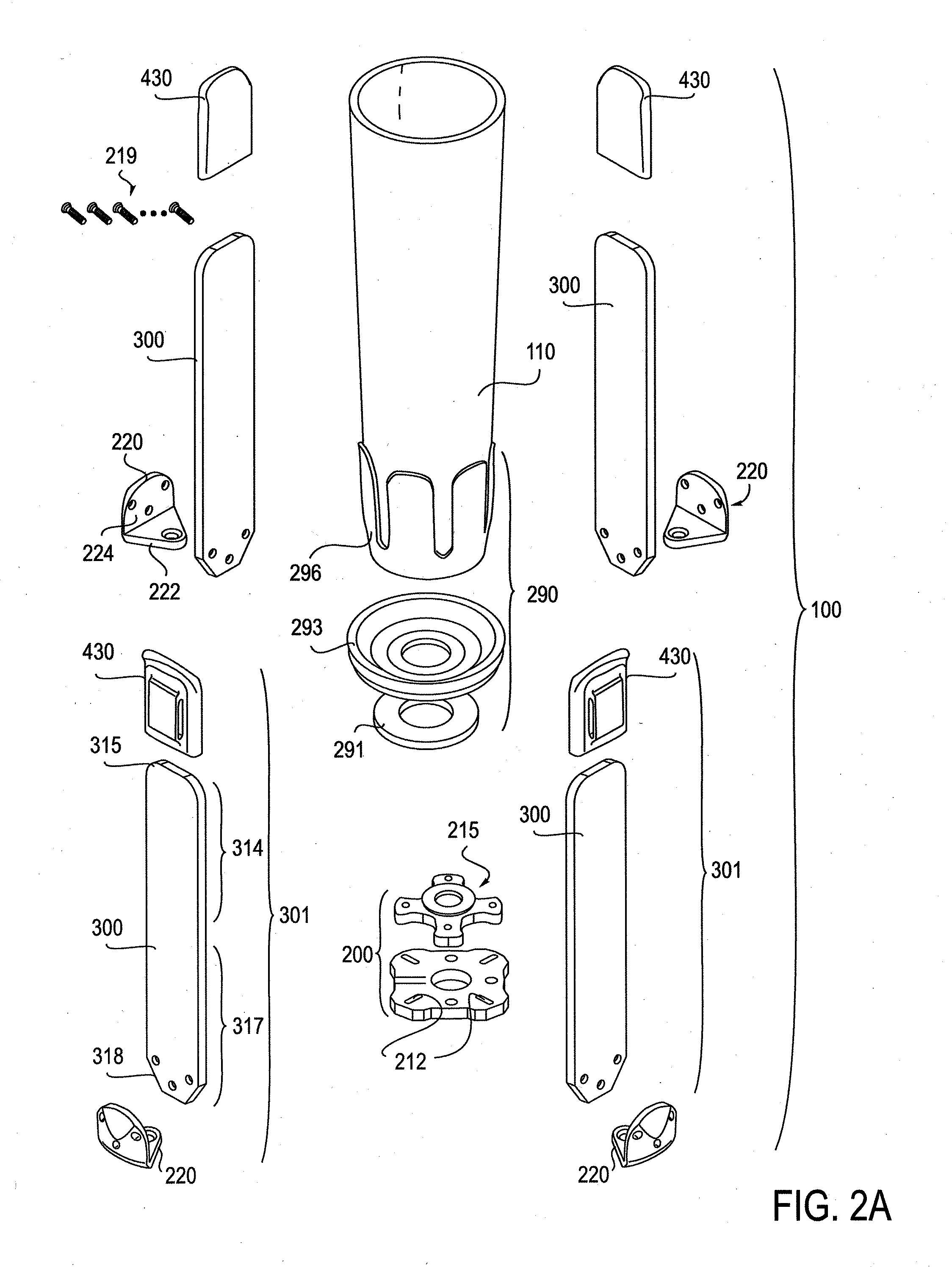
embodiment 200
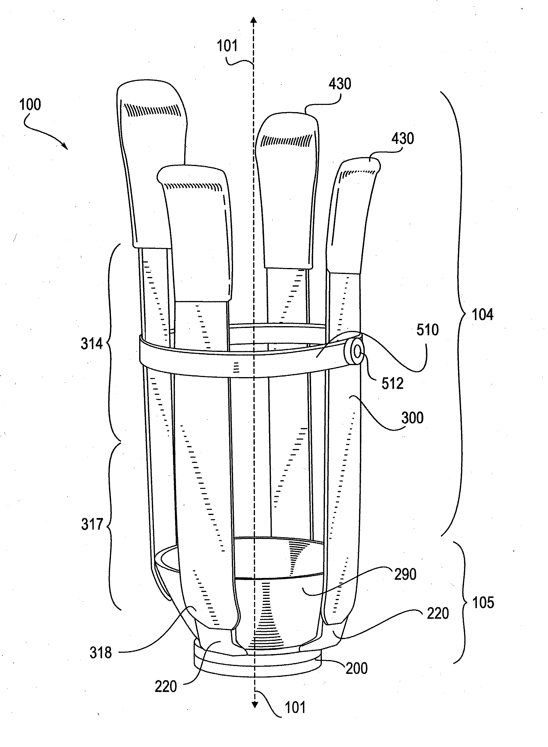
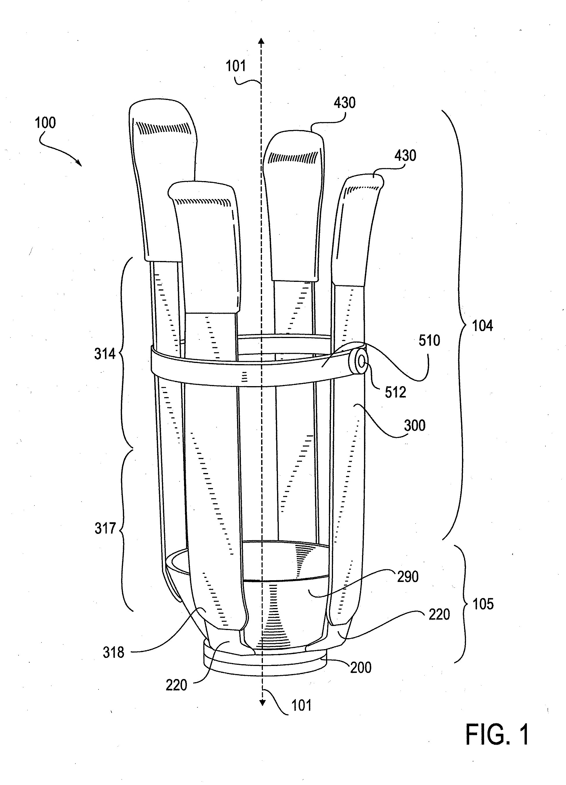
[0255]Struts 300 may also be divided into a proximal portion 314 and a distal portion 317. As with the socket 100 as a whole, these proximal 314 and distal 317 strut portions have no bright line demarcation, but are used for general orientation when describing the struts 300 or elements associated with them. Distal ends 318 of the struts 300 are connected or fastened to strut connectors 220. Details of the strut connectors 220 and their relationship to the distal base 200 and the struts 300 are detailed in FIGS. 16A-19 that follow. The proximal ends 315 of the struts 300 are not visible in FIG. 1, as they are covered by embodiments of strut caps 430. Strut caps 430 are included within a broader group of components referred to as pressure distributing elements. Other pressure distributing elements include brim elements 420 and a flexible inner liner 410, as depicted in FIGS. 22A-23C, and described below. An embodiment of a distal cup 290 is disposed above the distal base embodiment 2...
embodiment 300
[0278]FIGS. 7A-7D show a thermoplastic-fiber composite strut embodiment 300 and cross sectional views of a various optional cross sectional profiles. FIG. 7A shows a perspective view of a strut 300; FIGS. 7B-7D show example profiles such as inward-facing concave surface (FIG. 7B), a flat or rectangular cross section (FIG. 7C), and an oval cross section (FIG. 7D). These are non-limiting examples of many suitable cross sectional profiles. Modular components can vary in shape in addition to varying in dimension, while still maintaining common attachment features that allow them to be assembled with other components. The examples of variation in shape provided in FIGS. 7A-7D relate to variation in cross sectional profile that may occur in embodiments of struts 300. FIG. 7A provides a perspective view of a strut 300 that is similar to that seen in FIG. 5B. In typical strut embodiments 300, the distal end 318 of a strut has a substantially flat or rectangular cross-sectional profile, as s...
embodiment 305
[0312]FIGS. 19A and 19B show an embodiment of a strut 300 and an alternative embodiment 305 for inclusion in a modular prosthetic socket as described herein, each embodiment attached to a distal base 200. FIG. 19A shows a top perspective view of an embodiment of a distal base 200 similar to that of FIG. 14G with a with a single strut 300 attached thereto by way of a strut connector 220; this view shows how a base plate 210 and a top plate 215 of base 200 can cooperate to provide a strut connecting site that further stabilizes the strut, and provides a boundary to the pivoting latitude. FIG. 19B shows an embodiment of a strut 305 with an integrated connector portion on its distal end.
[0313]FIGS. 20A-20D show side views of thermoplastic-fiber composite struts 300 that have a varying side profile, ranging from substantially straight to having two or more sites of curvature. Each strut has a proximal end 315 and a distal end 318. The strut 300 of FIG. 20A is straight, having no signific...
PUM
| Property | Measurement | Unit |
|---|---|---|
| Temperature | aaaaa | aaaaa |
| Temperature | aaaaa | aaaaa |
| Temperature | aaaaa | aaaaa |
Abstract
Description
Claims
Application Information