Attachment bracket for use with heavy machinery and bracket members

a technology for attaching brackets and heavy machinery, which is applied in the direction of towing devices, soil shifting machines/dredgers, construction, etc., can solve the problems of not being the best way to move things around and not being easy to move around, and achieve the effect of limiting rotational movemen

Inactive Publication Date: 2014-09-25
CLOUTIER ALAIN
View PDF7 Cites 6 Cited by
  • Summary
  • Abstract
  • Description
  • Claims
  • Application Information

AI Technical Summary

Benefits of technology

[0008]Two attachment pins respectively located on distal end portions of the movable members and are adapted to respectively rotationally and removably engage with the pair of arms, and two limiting rods respectively located on middle sections of the movable members and are adapted to respectively engage middle portions of the pair o

Problems solved by technology

The problem with those bins is that they are not easy to move around.
Sometimes

Method used


Image

  • Attachment bracket for use with heavy machinery and bracket members
  • Attachment bracket for use with heavy machinery and bracket members
  • Attachment bracket for use with heavy machinery and bracket members

Examples


Embodiment Construction

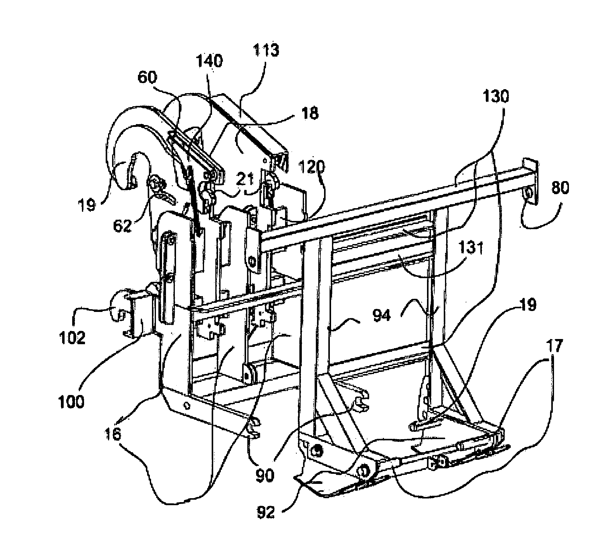
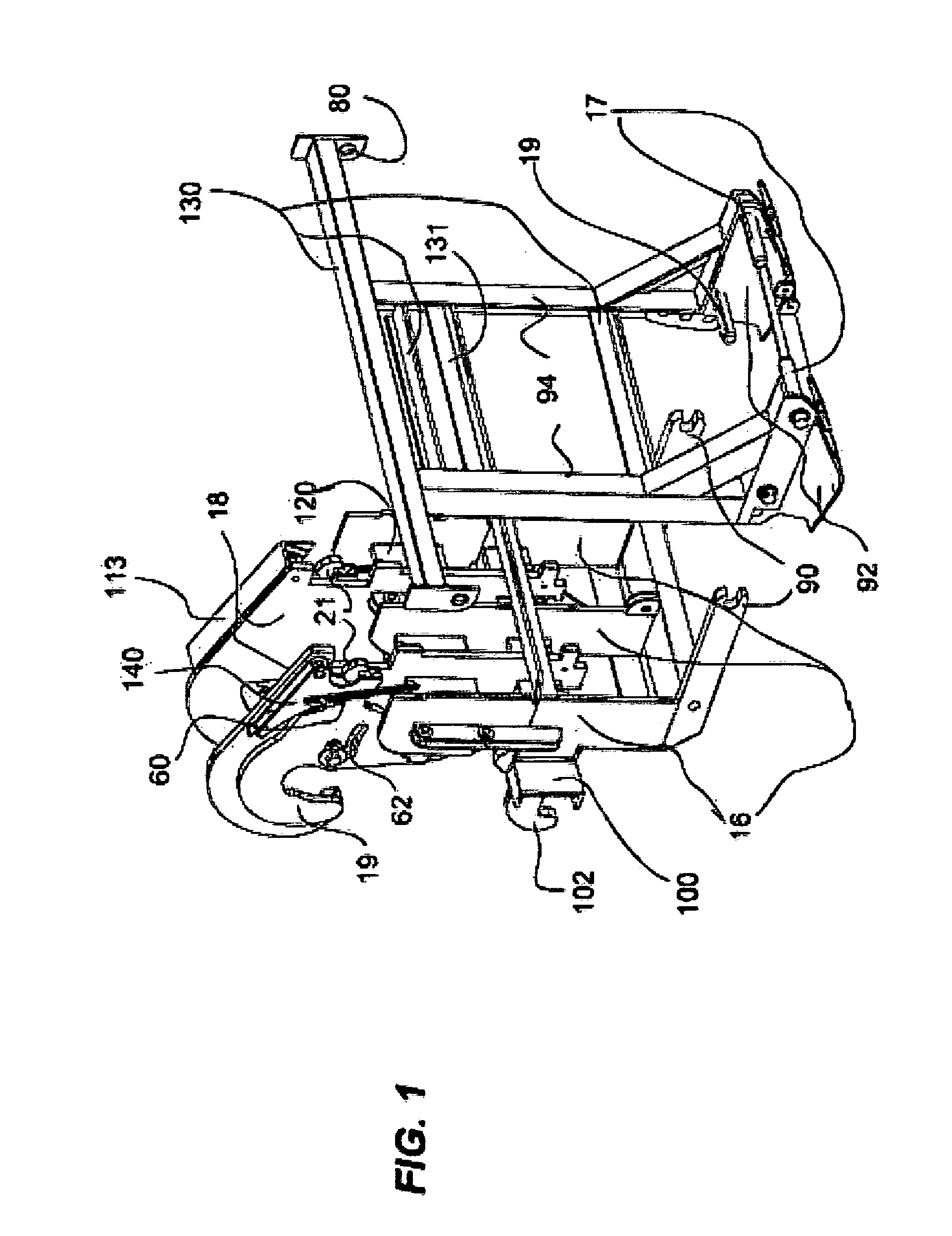
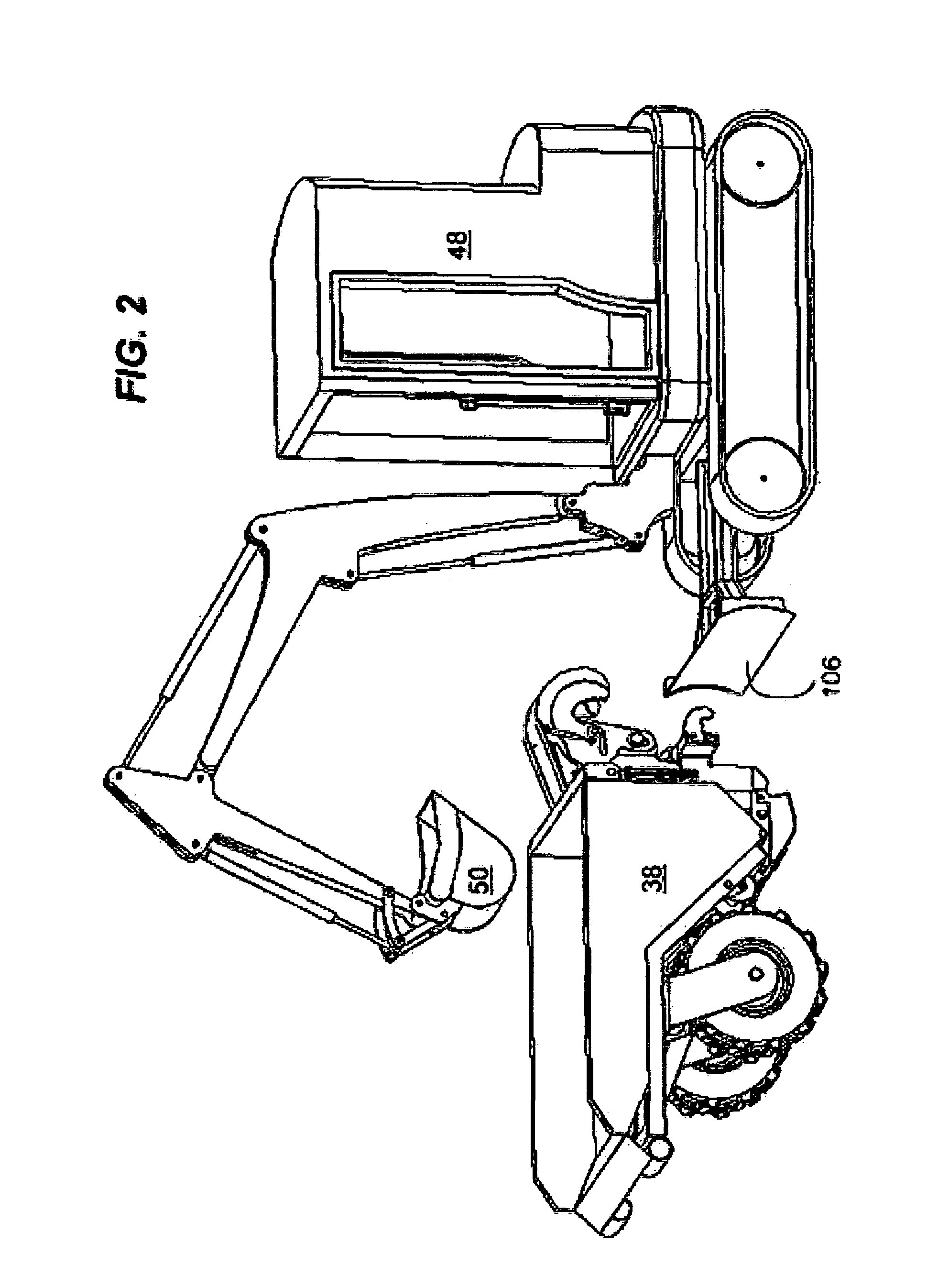
[0028]An attachment bracket (10) for use on heavy machinery such as excavators (48), for example, and to which is releasably attached a double wheeled bin (38) having a pair of wheels (34), and a frame (42).

[0029]The attachment bracket (10) consists in bracket frame members (16), a pair of main hooks (18) with each main hook (18) rotationally attached to a secondary hook (19). The secondary hooks (19) are biased into a rest configuration by way of biasing means (60).

[0030]The attachment bracket (10) has a pair of arms (90) located at the base of the frame members (16) which are rotationally attached to attachment pins (17) which extend from skids (92). Limiting rods (19) limit the rotation of movable members (94) by resting on top of the arms (90). The movable members (94) form part of the frame (42) and are rotatable in relation to the skids (92) but fixed in relation to the bin (38).

[0031]Pistons (96) are used as are used shock absorbers with coil springs in suspension systems and...


PUM


Abstract

An attachment bracket for use with heavy machinery and adapted to releasably attach to a double wheeled bin. The attachment bracket has a plurality of spaced parallel elongated bracket frame members, an elongated wide plate member connected to each the bracket frame member forming a rigid connection therebetween, a pair of spaced main hook members removably and adjustably connected to the wide plate member in between the bracket frame members, and a pair of secondary hook members, each rotationally connected to a respective the main hook member and biased such that they will return to an initial position when not being forced to rotate.

Description

[0001]This application claims priority based on request GB1204803.9 filed Mar. 19, 2012FIELD OF THE INVENTION[0002]The present invention relates generally to construction equipment but more particularly to an attachment bracket for use with heavy machinery and bracket members.BACKGROUND OF THE INVENTION[0003]Quite often on a construction site a bin is used for loading and carrying material from place to place around the site. Sometimes the bin used for temporarily storing aggregate material such as dirt or gravel for later use. The problem with those bins is that they are not easy to move around. Sometimes they are dragged on the ground, which is not the best way to move things around. There has to be a better and more efficient way of doing this.SUMMARY OF THE INVENTION[0004]In view of the foregoing disadvantages inherent in the known devices now present in the prior art, the present invention, which will be described subsequently in greater detail, is to provide objects and advant...

Claims


Application Information

Patent Timeline
IPC IPC(8): B60D1/04E02F9/00
CPCE02F9/00B60D1/04E02F3/3618E02F3/3686E02F3/962
Inventor CLOUTIER, ALAIN
Owner CLOUTIER ALAIN
Why Eureka
Try Eureka