Fusing device and eletrophotographic image forming apparatus

Active Publication Date: 2014-10-02
HEWLETT PACKARD DEV CO LP
View PDF4 Cites 5 Cited by
  • Summary
  • Abstract
  • Description
  • Claims
  • Application Information

AI Technical Summary

Benefits of technology

[0009]The present general inventive concept provides a fusing device th

Problems solved by technology

The fusing device conventionally has a low heating efficiency, because

Method used


Image

  • Fusing device and eletrophotographic image forming apparatus
  • Fusing device and eletrophotographic image forming apparatus
  • Fusing device and eletrophotographic image forming apparatus

Examples


Example

[0043]Reference will now be made in detail to the embodiments of the present general inventive concept, examples of which are illustrated in the accompanying drawings, wherein like reference numerals refer to the like elements throughout. The embodiments are described below in order to explain the present general inventive concept while referring to the figures.

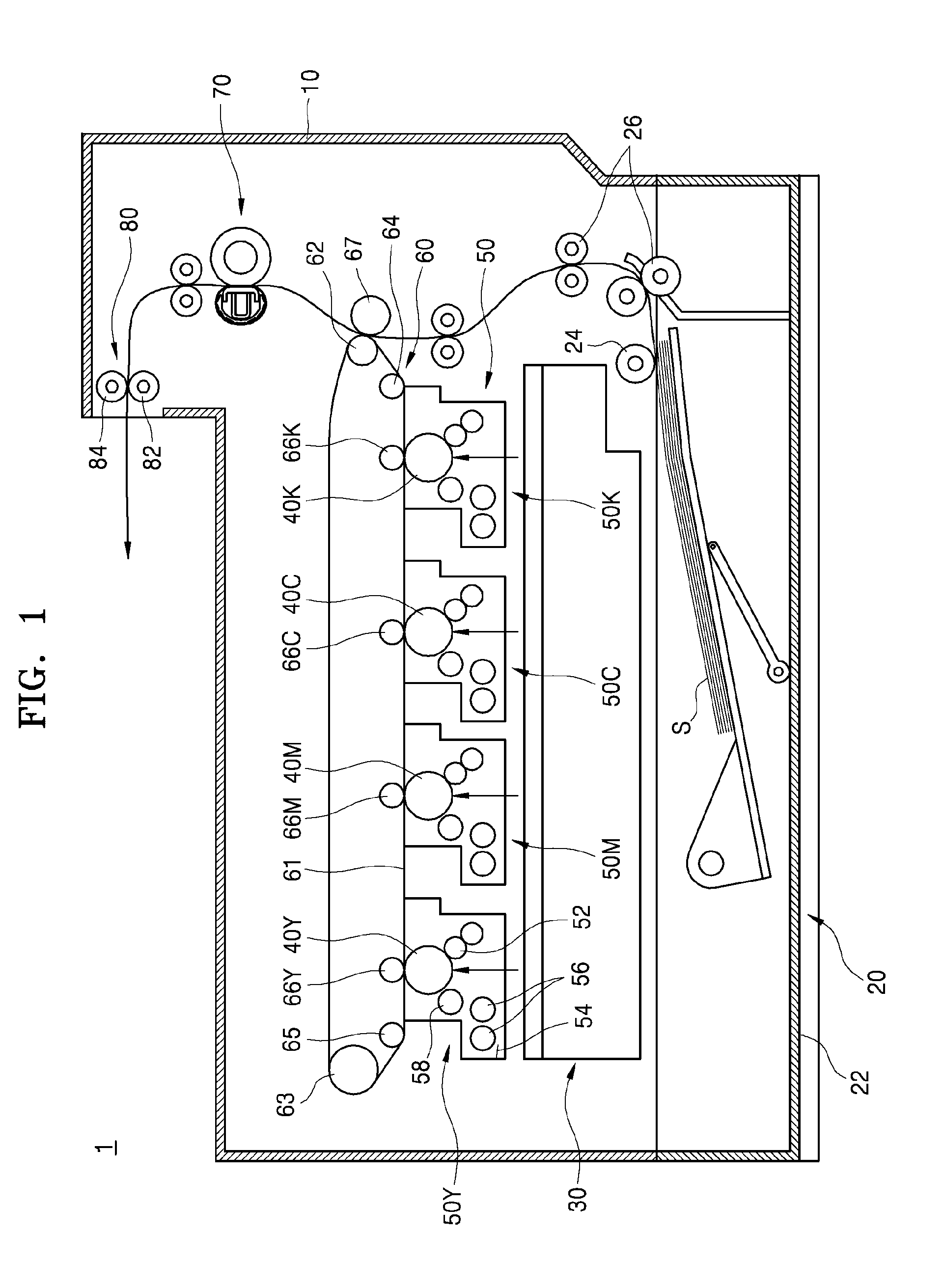
[0044]FIG. 1 is a schematic view illustrating an electrophotographic image forming apparatus 1 according to an exemplary embodiment of the present general inventive concept.

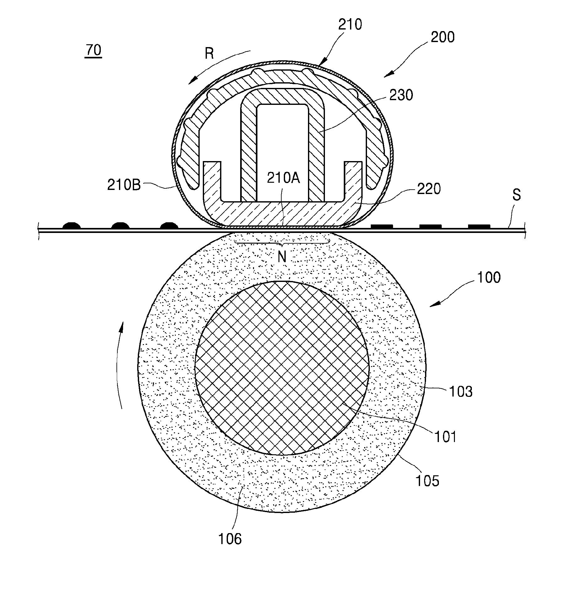
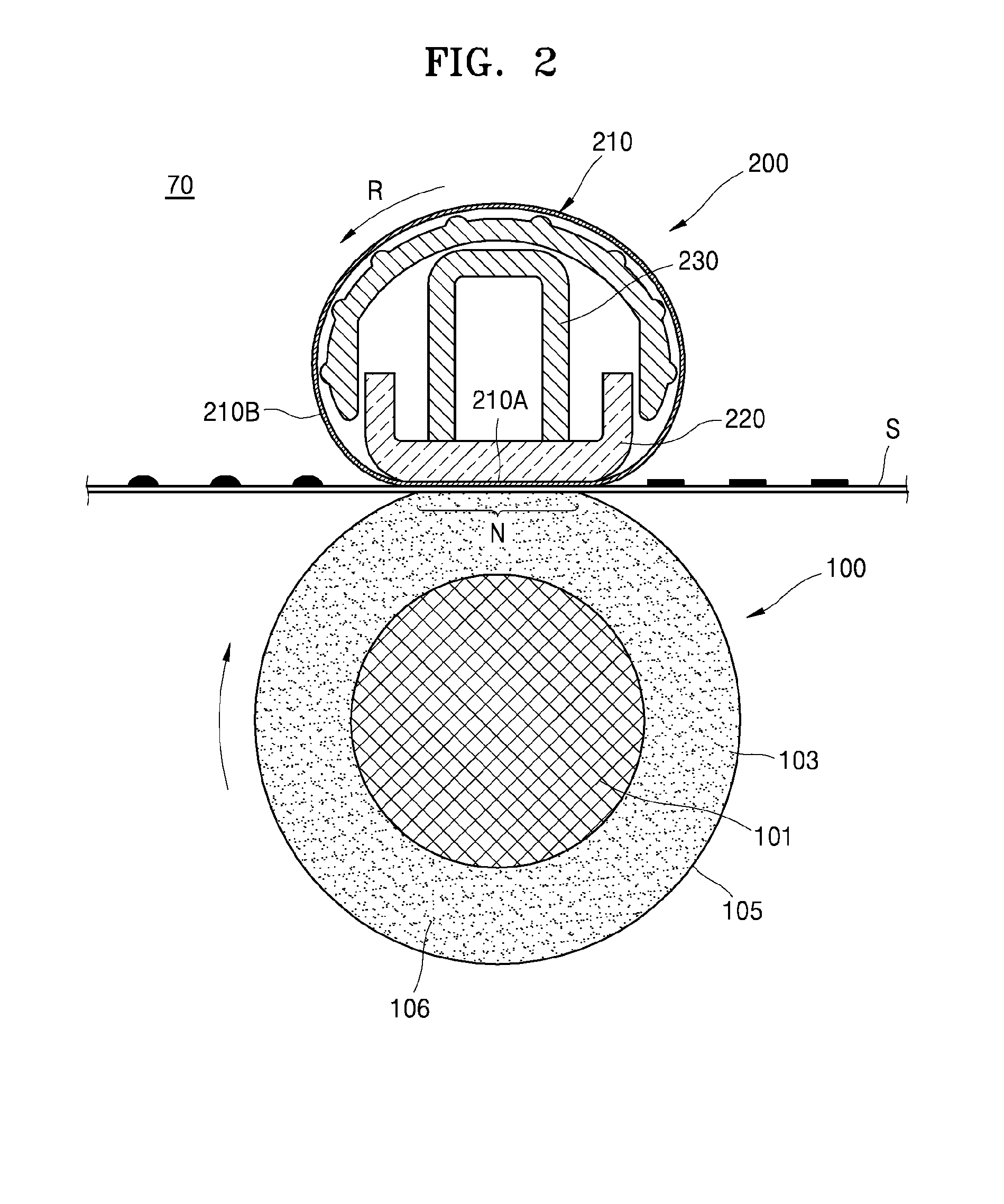
[0045]As illustrated in FIG. 1, the electrophotographic image forming apparatus 1 (hereinafter “the image forming apparatus 1”) includes a main body 10, a recording medium supply unit 20, a light scanning unit 30, a plurality of photosensitive media 40Y, 40M, 40C, and 40K, respectively, a developing unit 50, a transfer unit 60, a fusing unit 70, and a recording medium discharge unit 80.

[0046]The main body 10 is an outer case of the image forming apparatus ...


PUM


Abstract

A fusing device according to an embodiment of the present general inventive concept includes a pressing unit, a heating fusing belt contacts an outer surface of the pressing unit and rotates, a nib forming unit contacts an inner surface of the heating fusing belt and forms a nib at a contact portion between the pressing unit and the heating fusing belt, a first guide unit disposed at both end portions of the heating fusing belt so as to guide the movement of the heating fusing belt, and a second guide unit disposed between the first guide units and having a plurality of ribs which are arranged spaced apart from each other along a rotational direction of the heating fusing belt, so as to guide the movement of a central portion of the heating fusing belt.

Description

CROSS-REFERENCE TO RELATED APPLICATIONS[0001]This application claims priority under 35 U.S.C. §119 (a) from Korean Patent Application No. 10-2013-0032364, filed on Mar. 26, 2013, in the Korean Intellectual Property Office, the disclosure of which is incorporated herein by reference in its entirety.BACKGROUND OF THE INVENTION[0002]1. Field of the Invention[0003]The present general inventive concept relates to a fusing device that fuses a toner image transferred onto a recording medium by using heat and pressure, and an electrophotographic image forming apparatus including the same.[0004]2. Description of the Related Art[0005]An electrophotographic image forming apparatus forms a latent image on a surface of a photosensitive medium by irradiating light demodulated according to image information onto the photosensitive medium and forms a visible toner image by supplying toner to the latent image. Then, the toner image is transferred onto a recording medium and fused on the recording me...

Claims


Application Information

Patent Timeline
IPC IPC(8): G03G15/20
CPCG03G15/2064G03G2215/2035G03G2215/0132G03G15/2053
Inventor JEON, SANG-UK
Owner HEWLETT PACKARD DEV CO LP
Why Eureka
Try Eureka