Variable duct apparatus for vehicle

a duct apparatus and vehicle technology, applied in lighting and heating apparatus, ventilation systems, heating types, etc., can solve problems such as affecting the normal operation of the engine, affecting the warm-up performance of the engine and the catalytic activity of the exhaust gas purifier device in the winter, and causing the introduction of air to be blocked or reduced

Active Publication Date: 2014-10-02
SUBARU CORP
View PDF6 Cites 23 Cited by
  • Summary
  • Abstract
  • Description
  • Claims
  • Application Information

AI Technical Summary

Benefits of technology

[0017]A first aspect of the invention provides a variable duct apparatus for a vehicle including: a first louver and a second louver that are disposed at a front of a vehicle and configured to rotate respectively around a first axis and a second axis up to an open position and a closed position, the first axis and the second axis extending in the vehicle width direction, the open position allowing air to be introduced into the vehicle front, the closed position causing the introduction of air to be blocked or reduced; a link to connect the first louver and the second louver in an interlocking manner; a first stopper and a second stopper that are respectively disposed at the first louver and the second louver and configured to come into contact with each other to control the first louver and the second louver at the open position; an electric motor to rotationally drive the first louver; and a control device to perform an opening operation for rotating the first louver up to the open position and a closing operation for rotating the first louver up to the closed position by supplying current to the electric motor until a lock current value is detected. The control device includes an abnormality determining unit to determine that an operating state is abnormal when an operating angle of the first louver from a start of either one of the opening operation and the closing operation until the detection of the lock current value is out of a predetermined reference operating angle range.

Problems solved by technology

The engine may be excessively cooled in the winter or in a cold region or during continuous high speed running.
In addition, the warm-up performance of the engine and the catalytic activity of an exhaust gas purifier device may be affected in the winter or in a cold region.
Thus, even if a movable fin other than the movable fin in contact with the prevention unit falls off, or a unit for interlocking the movable fins has a failure, the operation is normal may be erroneously determined to be normal.
In addition, since the prevention unit, which projects from the case frame, receives a heavy load due to contact with the movable fins at the open position, rigidity for preventing deformation of the case frame is necessary, and thus the shape of the case frame is limited.
Thus, even if an operation of the plate vanes has a failure, for example, a plate vane falls off, or a joint connecting the slide link and the plate vanes falls off, erroneous determination indicating that the operation may erroneously be determined to be normal.

Method used


Image

  • Variable duct apparatus for vehicle
  • Variable duct apparatus for vehicle
  • Variable duct apparatus for vehicle

Examples


Embodiment Construction

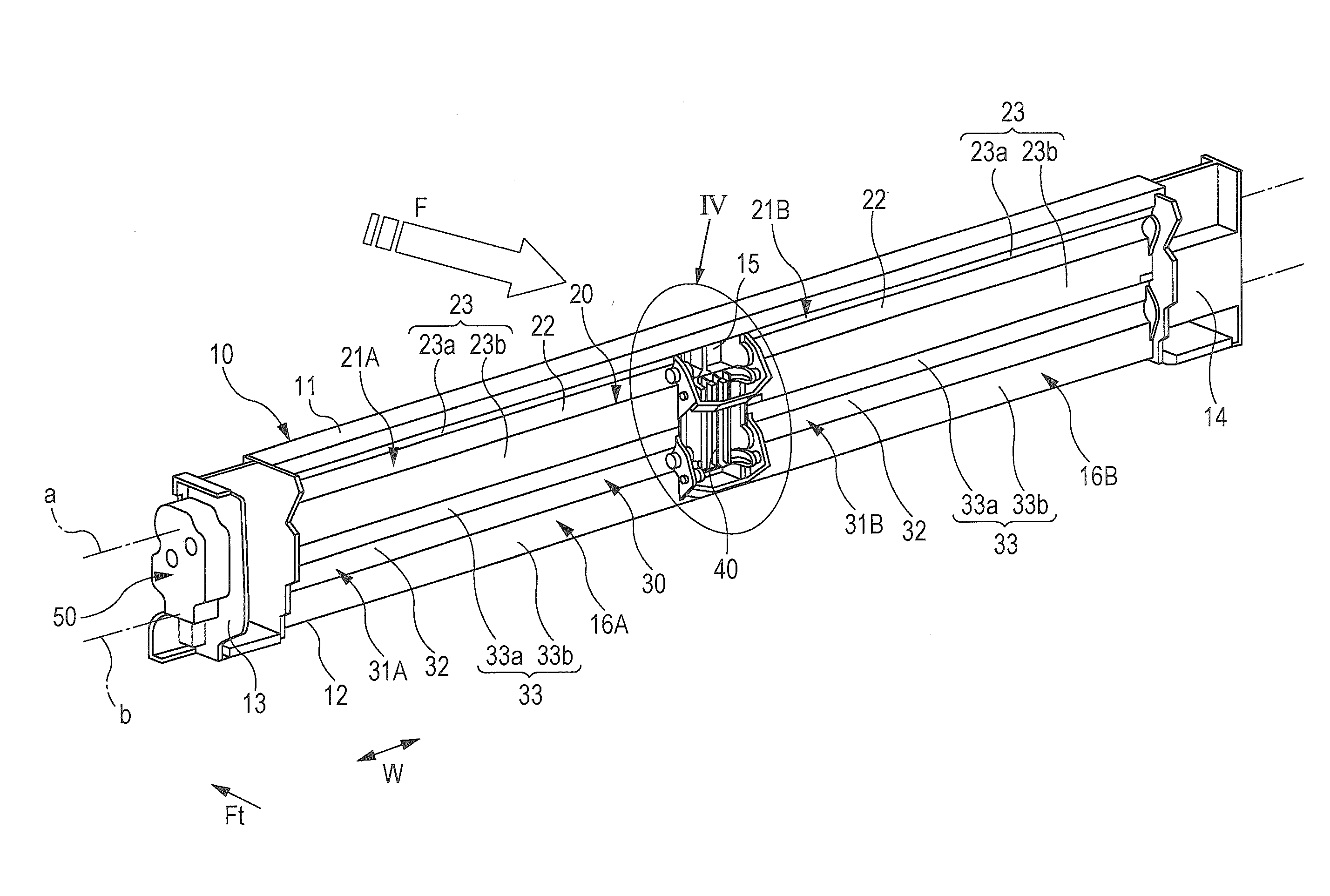
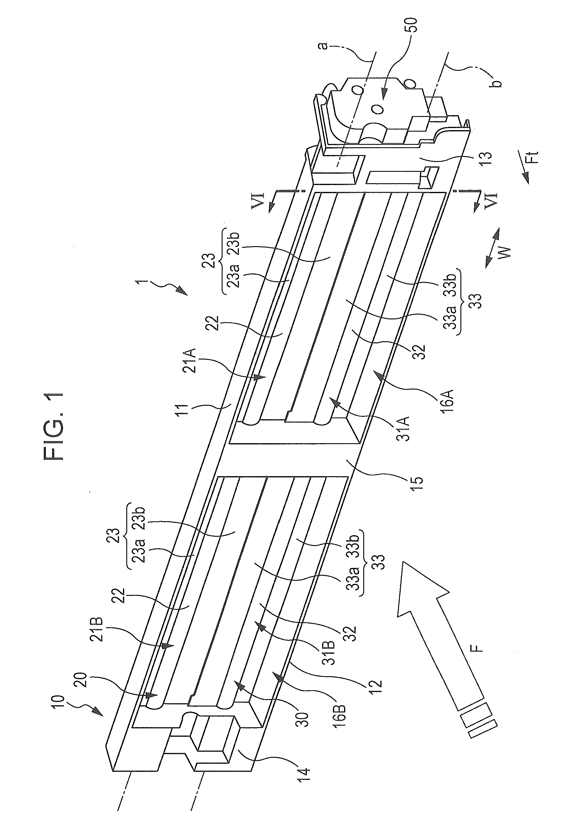
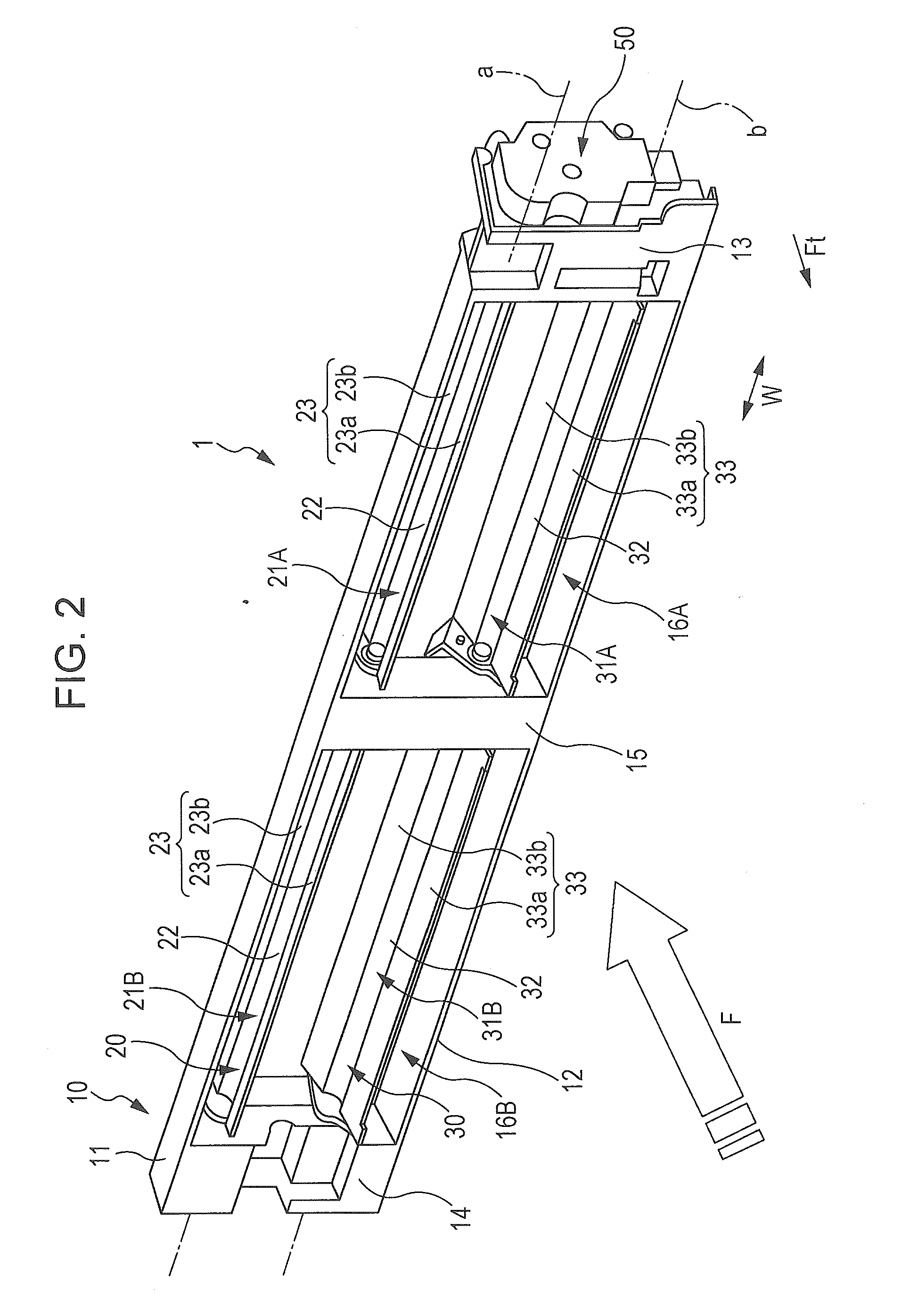
[0028]Hereinafter, a variable duct apparatus for a vehicle according to an implementation will be described with reference to FIGS. 1 to 8.

[0029]FIG. 1 is an upper front perspective view of a variable duct apparatus 1 in a fully closed state according to an implementation; FIG. 2 is an upper front perspective view of the variable duct apparatus 1 in a fully open state; FIG. 3 is an upper rear perspective view of the variable duct apparatus 1 in a fully closed state; FIG. 4 is an enlarged view of portion IV of FIG. 3; and FIG. 5 is an exploded perspective view of the variable duct apparatus 1. FIG. 6A is a cross-sectional view of the variable duct apparatus 1 taken along line VI-VI in a fully closed state; and FIG. 6B is a cross-sectional view of the variable duct apparatus 1 taken along line VI-VI in a fully open state. FIG. 7 is a block diagram illustrating the control system of the variable duct apparatus 1. In the figures, arrow Ft indicates the direction to the front of the vehi...


PUM


Abstract

A variable duct apparatus for a vehicle including first and second louvers to rotate around first and second axes to open and closed positions, the variable duct apparatus including: a link to connect first and second louvers; first and second stoppers disposed at the first and second louvers to control the first and second louvers at an open position; a motor to rotate the first louver; and a control device to perform an opening or closing operation for rotating the first louver to the open or closed position by supplying current to the electric motor until a lock current is detected. The control device includes an abnormality determining unit to determine that an operating state is abnormal when an operating angle of the first louver from a start of the opening or closing operation until detection of the lock current is out of a predetermined reference operating angle range.

Description

CROSS-REFERENCE TO RELATED APPLICATIONS[0001]The present application claims priority from Japanese Patent Application No. 2013-067936 filed on Mar. 28, 2013, the entire contents of which are hereby incorporated by reference.BACKGROUND[0002]1. Technical Field[0003]The present invention relates to a variable duct apparatus for a vehicle disposed at the front of the vehicle to adjust the amount of air to be introduced into the front of the vehicle.[0004]2. Related Art[0005]In general, the bumper and / or the front grille which are disposed at the front of a vehicle have an open air grille for introducing air into the front face of a radiator disposed at the front of the vehicle. The air introduced through the air grille cools coolant in the radiator.[0006]During high speed running, running resistance increases as the amount of air introduced into the front of the vehicle through the open air grille of the bumper and / or the front grille increases, whereby fuel efficiency may be reduced. T...

Claims


Application Information

Patent Timeline
Patent Type & Authority Applications(United States)
IPC IPC(8): F01P1/08
CPCF01P1/08B60K11/085F01P2031/00Y02T10/88
Inventor HIJIKATA, KENJI
Owner SUBARU CORP
Why Eureka
Try Eureka