

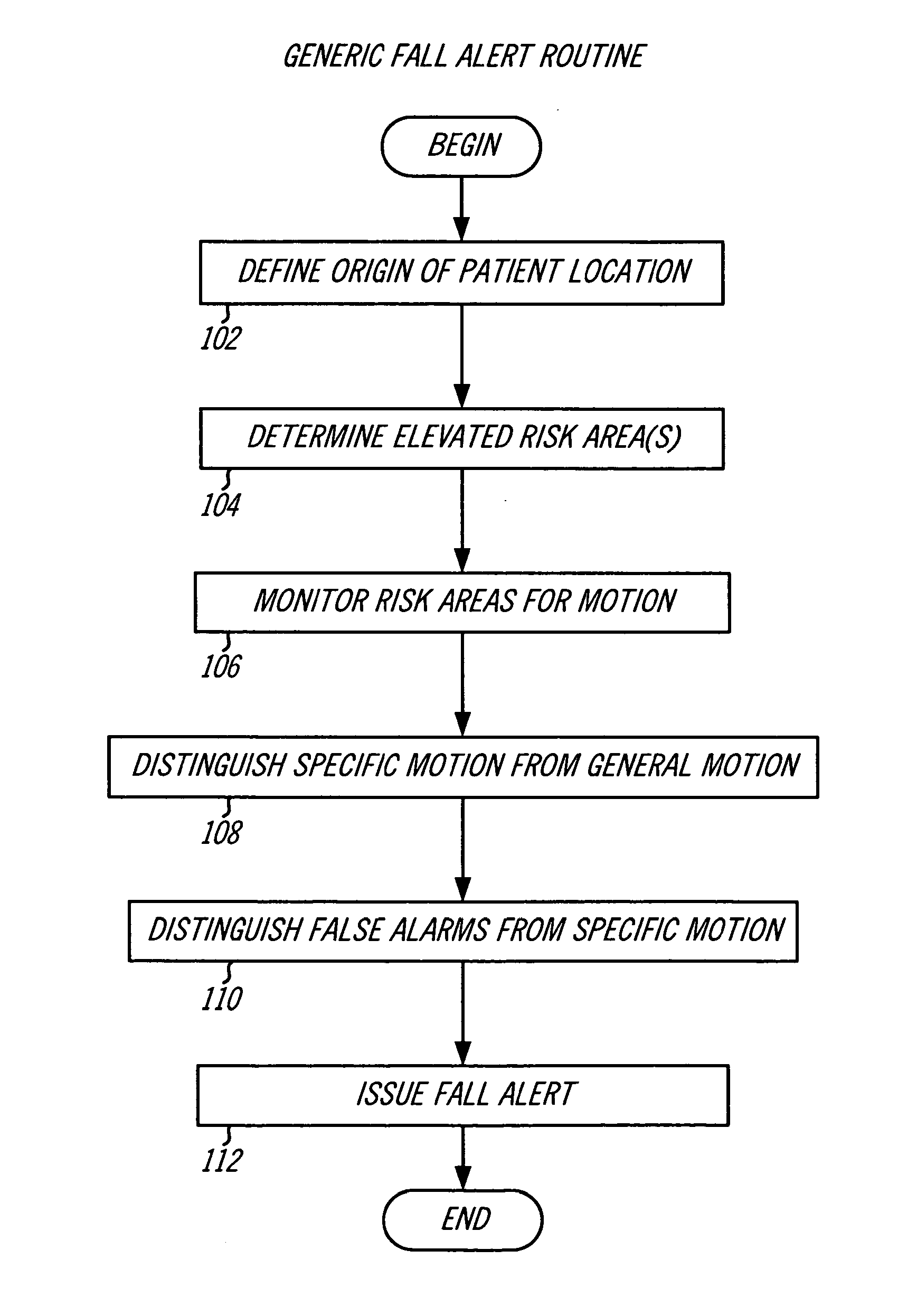
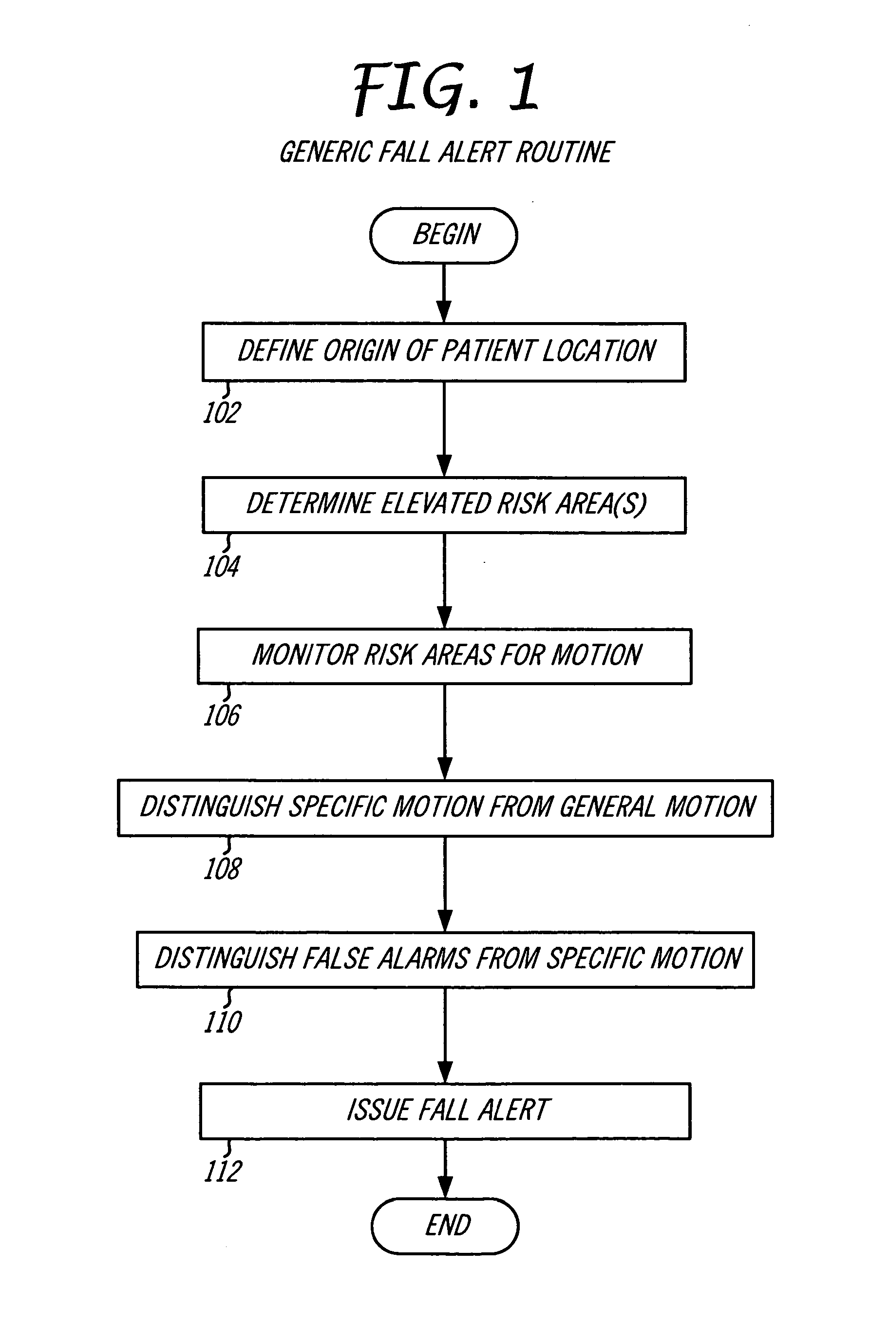
System and method for predicting patient falls
a patient and system technology, applied in the field of patient monitors, can solve problems such as the severity of the injury, the inability to know for sure which patient will fall, and the extensive scrutiny of bed falls
- Summary
- Abstract
- Description
- Claims
- Application Information
AI Technical Summary
Problems solved by technology
Method used
Image

Examples
Embodiment Construction
Element Reference Number Designations
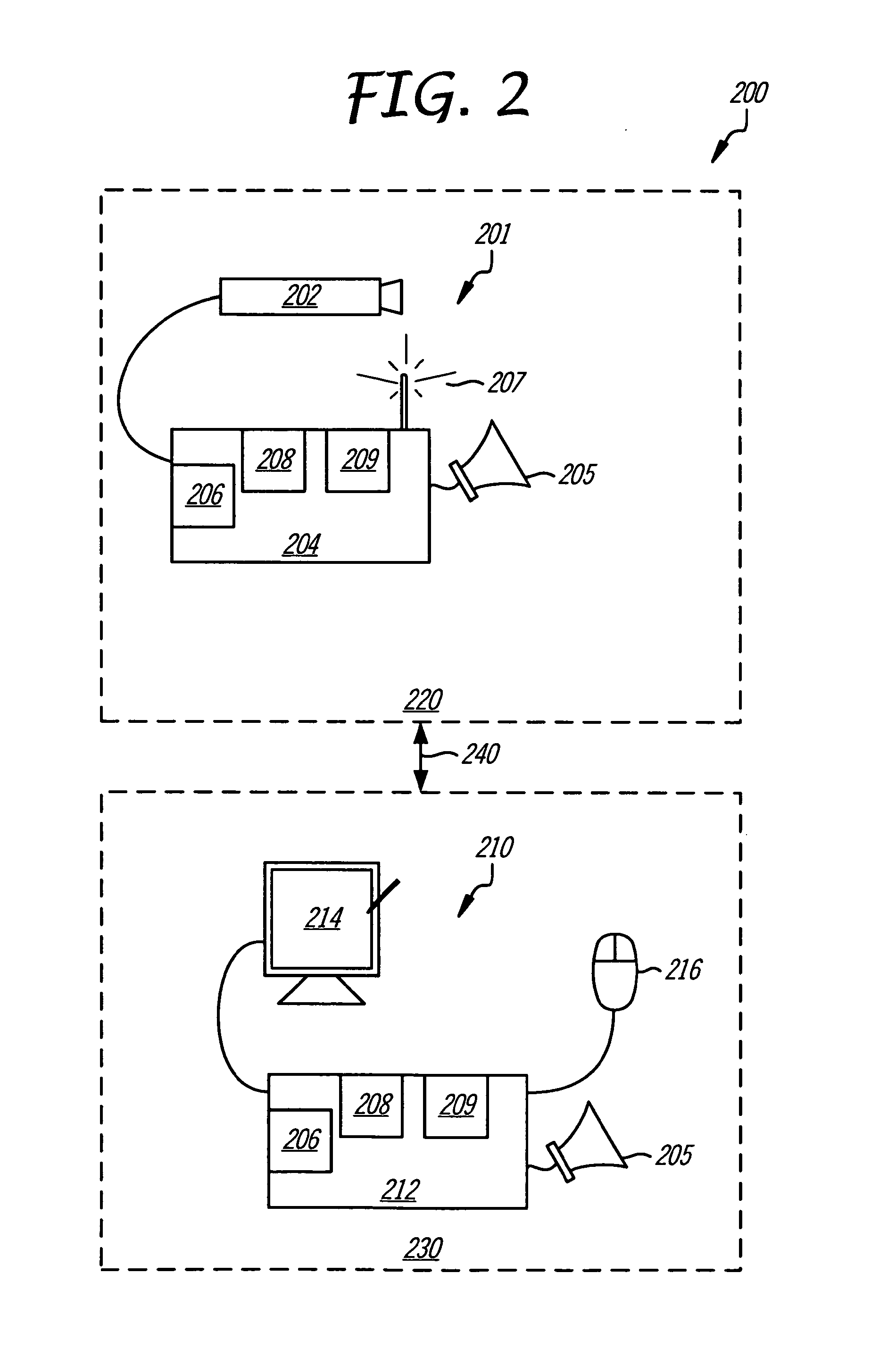
[0027]200: Patient monitoring system[0028]201: Patient monitoring device[0029]202: Video camera[0030]204: Camera control device[0031]205: Audible alarm[0032]206: Processor[0033]207: Receiver / interrigator[0034]208: Memory (RAM and ROM)[0035]209: Video processor[0036]210: Nurse monitor device[0037]212: Computer (PC, laptop, net device)[0038]214: Display (touch-screen)[0039]216: User interface device (mouse)[0040]220: Patient room[0041]230: Care (Nurse) station[0042]240: Distribution network[0043]321: Bed[0044]322: Wall[0045]324: Night stand[0046]326: Chair[0047]327: Lavatory door[0048]329: Entry door[0049]341: Transmission medium[0050]342: Network switch[0051]343: Boradband connection[0052]345: Patient administration[0053]346: Network server / router / firewall[0054]348: Network system administration[0055]420: Patient room[0056]423: Ceiling[0057]425: Floor[0058]450: Image frame[0059]451: Image frame[0060]460: Orientation angle[0061]461: Orientation ang...
PUM
 Abstract
Description
Claims
Application Information