Optical communication apparatus

Inactive Publication Date: 2014-10-23
HON HAI PRECISION IND CO LTD
View PDF7 Cites 9 Cited by
  • Summary
  • Abstract
  • Description
  • Claims
  • Application Information

AI Technical Summary

Benefits of technology

The present disclosure relates to an optical communication apparatus that addresses the difficulty of accurately aligning the coupler and photoelectric unit in the optical communication apparatus. The technical effect of this patent is to provide an optical communication apparatus that includes a coupler and a photoelectric unit that can be easily aligned with each other, even if they are small in size.

Problems solved by technology

However, the coupler and the photoelectric unit usually have small sizes and it is difficult to align the coupler with the photoelectric unit.

Method used


Image

  • Optical communication apparatus
  • Optical communication apparatus
  • Optical communication apparatus

Examples


Embodiment Construction

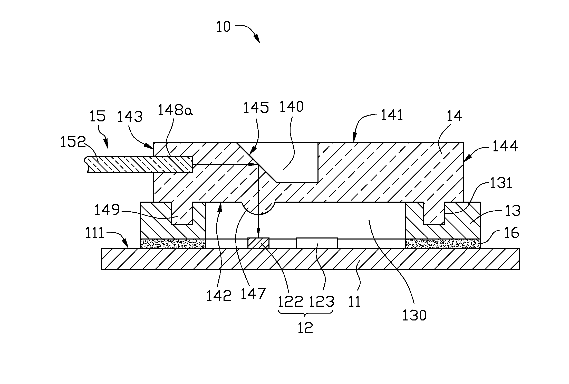
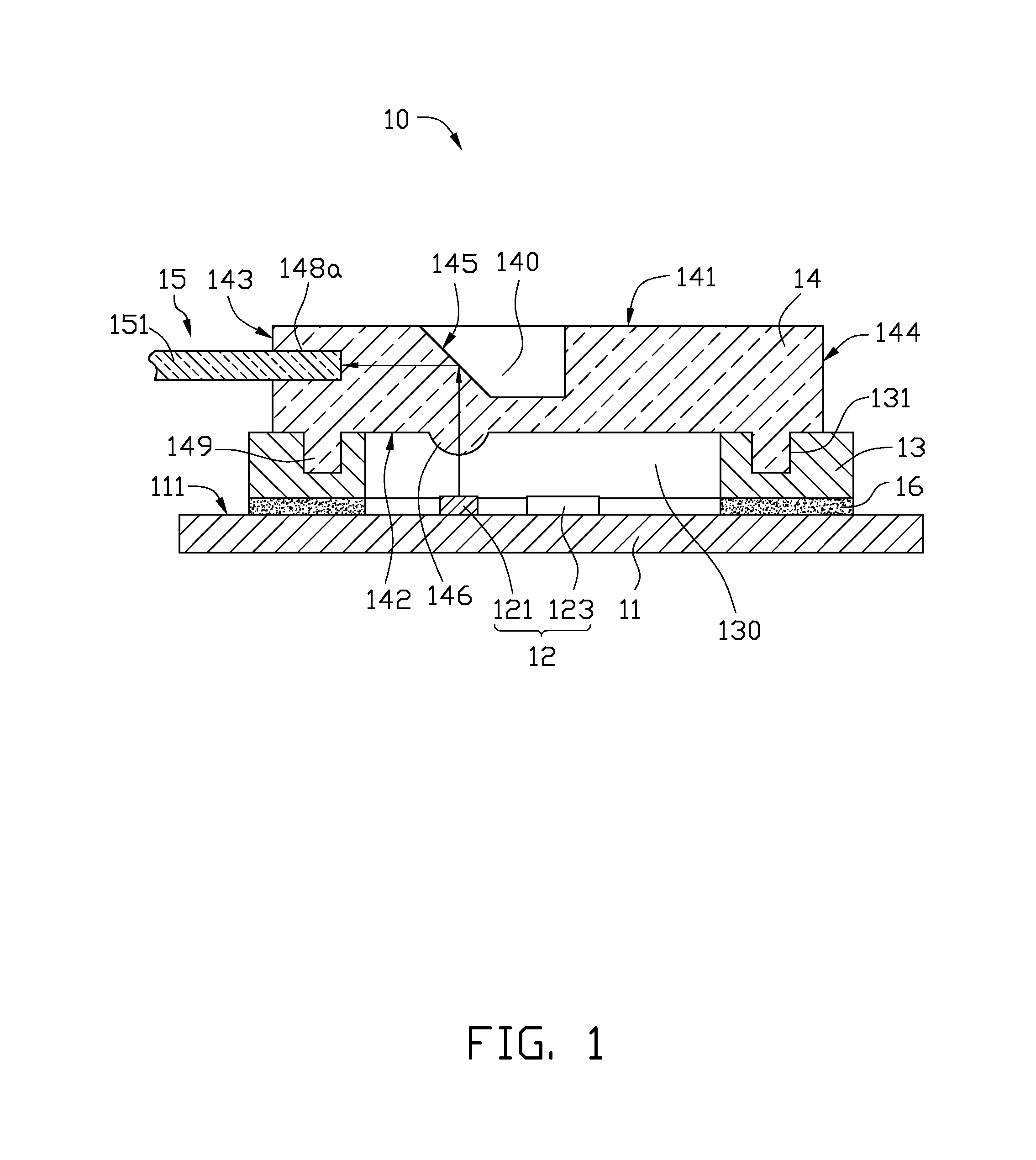
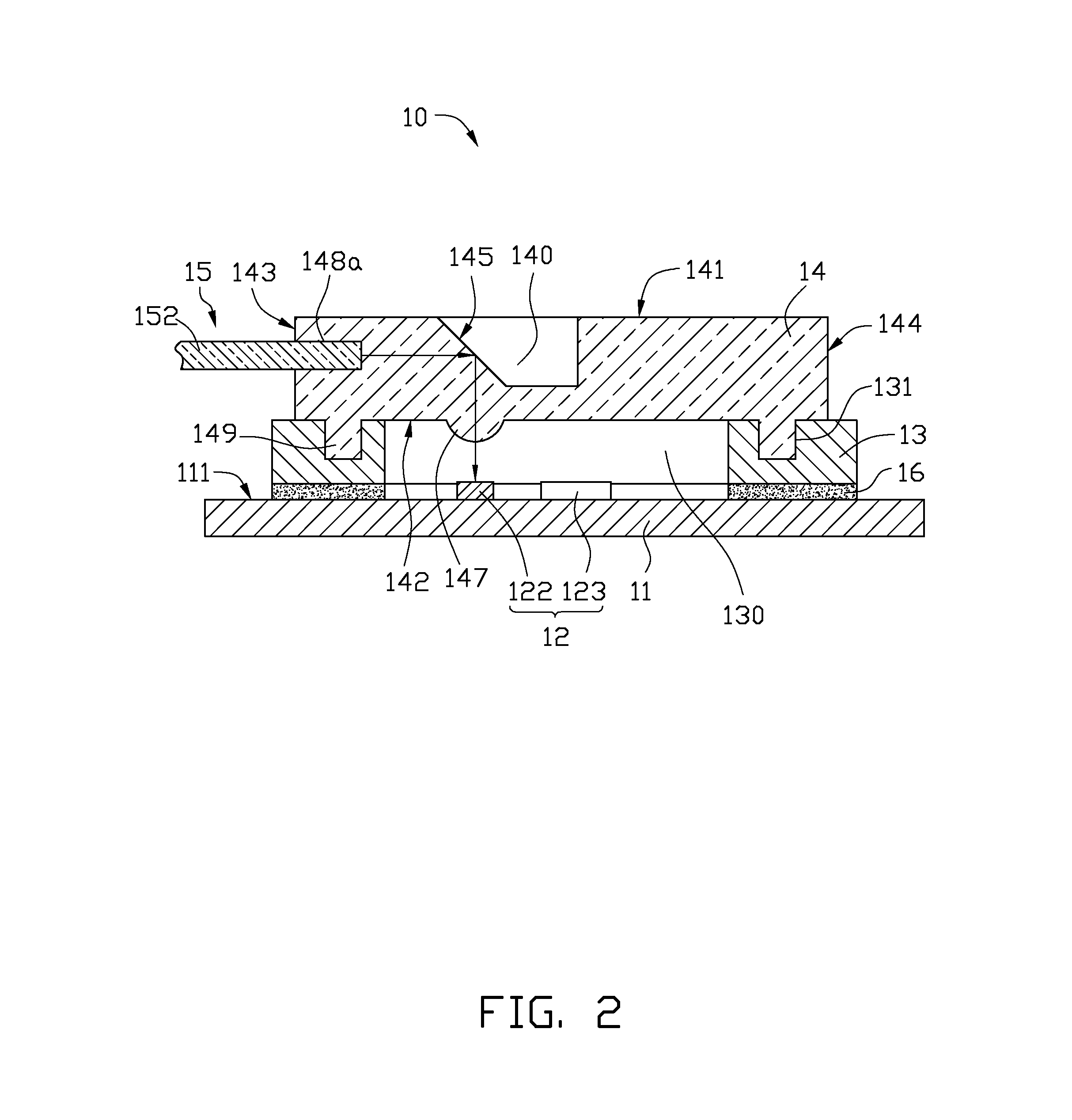
[0010]FIGS. 1-3 show one embodiment of an optical communication apparatus 10. The optical communication apparatus 10 includes a printed circuit board (PCB) 11, a photoelectric unit 12, a fixing board 13, a coupler 14, and an optical fiber unit 15. The photoelectric unit 12 and the fixing board 13 are fixedly positioned on the PCB 11, the coupler 14 is connected to the fixing board 13 covering the photoelectric unit 12, and the optical fiber unit 15 is connected to the coupler 14.

[0011]The PCB 11 can be a flexible PCB (FPCB), a rigid PCB or a rigid-flex compound PCB. The PCB 11 includes a mounting surface 111 supporting the photoelectric unit 12 and the fixing board 13.

[0012]The photoelectric unit 12 includes an emitter 121 for emitting optical signals and a receiver 122 for receiving optical signals. The emitting 121 and the receiver 122 are electrically connected to the PCB 11. In this embodiment, the emitter 121 can be a light emitting diode (LED) or a laser diode, and the receive...


PUM


Abstract

An optical communication apparatus includes a PCB, a photoelectric unit, a fixing board, a coupler, and an optical fiber unit corresponding to the photoelectric unit. The photoelectric unit is electrically connected to a surface of the PCB, the fixing board is securely positioned on the surface of the PCB, and the coupler unit is connected to the fixing board. The fixing board defines a through opening portion exposing the photoelectric unit. The coupler includes a lens unit corresponding to the photoelectric unit. One of the fixing board and the coupler defines a number of positioning holes, the other of the fixing board and the coupler includes a number of positioning poles corresponding to the positioning holes. The positioning poles are inserted into the corresponding positioning holes. The lens unit is aligned with the photoelectric unit by an engagement between the positioning poles and the positioning holes.

Description

BACKGROUND[0001]1. Technical Field[0002]The present disclosure relates to an optical communication apparatus.[0003]2. Description of Related Art[0004]Optical communication apparatuses include a coupler and a photoelectric unit. The coupler optically couples an optical fiber unit to the photoelectrical unit. To ensure an optical transmission efficiency of the optical communication apparatus, the coupler should be accurately aligned with the photoelectric unit. However, the coupler and the photoelectric unit usually have small sizes and it is difficult to align the coupler with the photoelectric unit.[0005]Therefore, what is needed is an optical communication apparatus addressing the limitations described.BRIEF DESCRIPTION OF THE DRAWINGS[0006]The components of the drawings are not necessarily drawn to scale, the emphasis instead being placed upon clearly illustrating the principles of the embodiments of the present disclosure. Moreover, in the drawings, like reference numerals design...

Claims


Application Information

Patent Timeline
IPC IPC(8): H04B10/40H04B10/25
CPCH04B10/25H04B10/40G02B6/4214G02B6/423G02B6/4246G02B6/428
Inventor SHEU, YI-ZHONG
Owner HON HAI PRECISION IND CO LTD
Why Eureka
Try Eureka