
Bony structure fixation clamp

a technology of fixing clamps and bony structures, applied in the field of bony structure fixation clamps, can solve problems such as nerve root injuries, spinal fluid, nerve root injuries,

Inactive Publication Date: 2014-10-23
NLT SPINE
View PDF0 Cites 15 Cited by
  • Summary
  • Abstract
  • Description
  • Claims
  • Application Information

AI Technical Summary

Benefits of technology

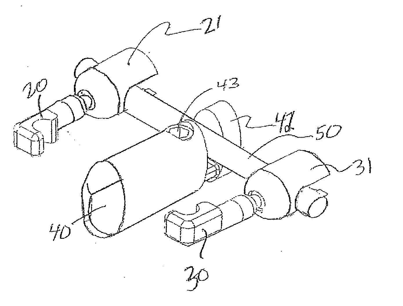
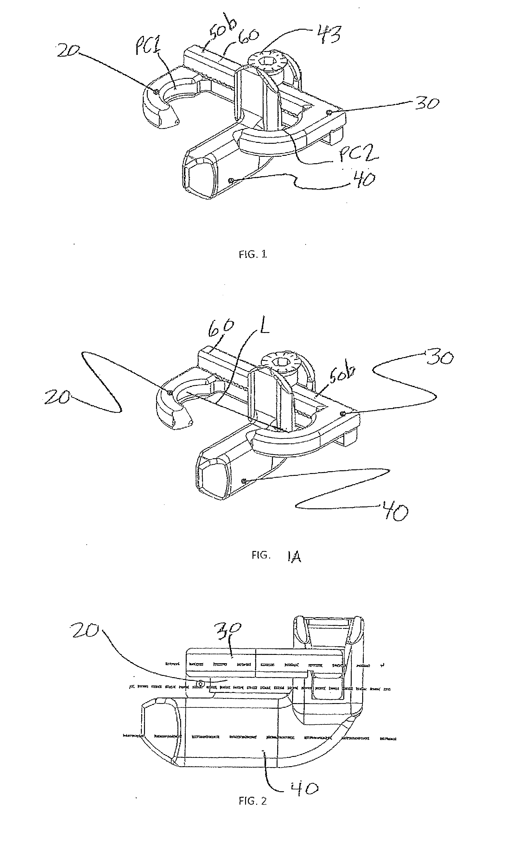
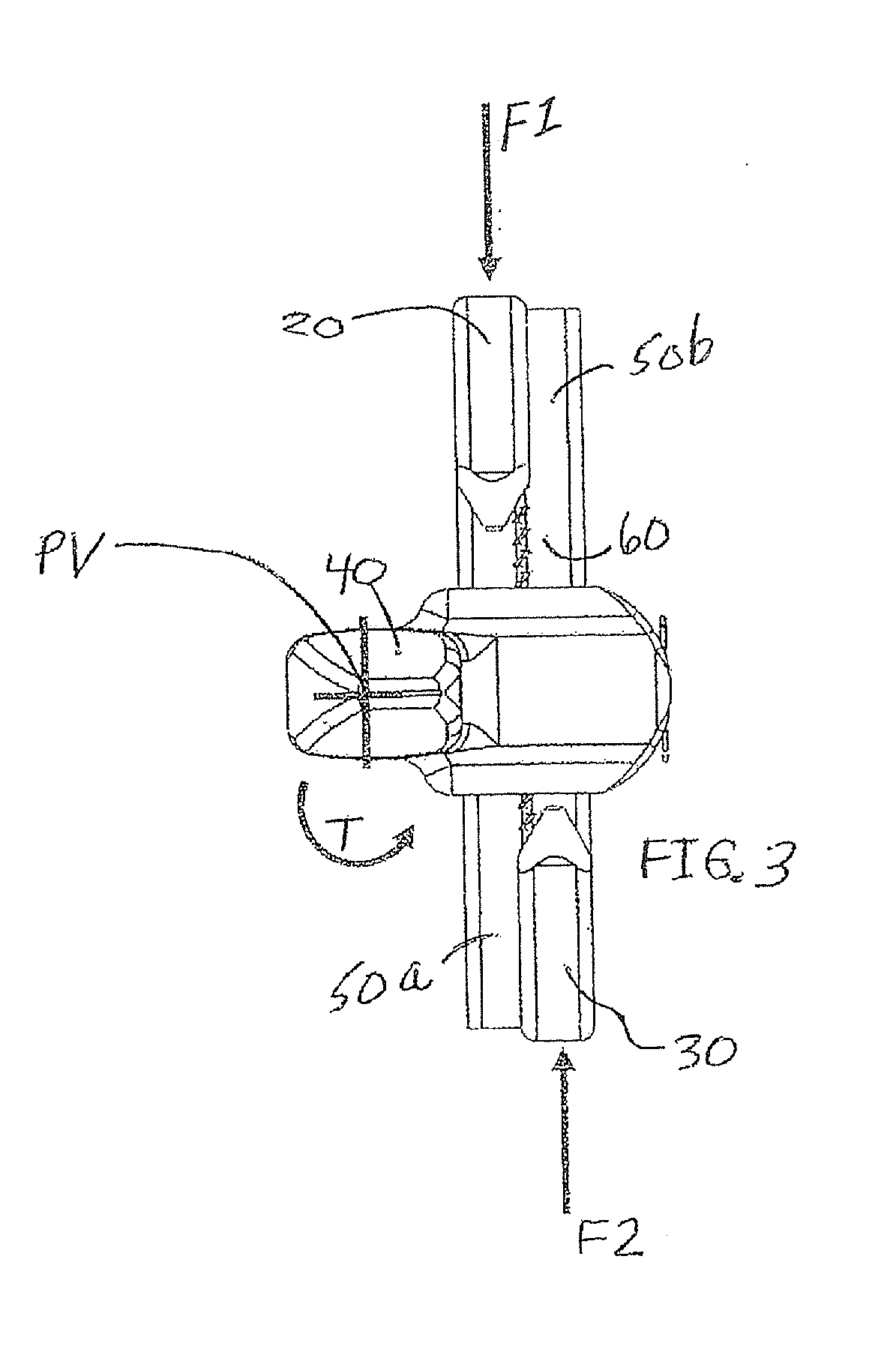
The present invention is a clamp that can be used to hold two bones in position. The clamp has two structures that are connected together and a spacer pivot that is positioned between the bones. The spacer pivot has a pivot point that is offset in either an anterior or posterior direction relative to the line of force exerted by the two structures. This allows for precise positioning of the clamp and ensures that the bones are held securely. The invention also includes a method for using the clamp and a multiple level clamp that can hold three bones in position.

Problems solved by technology

However, there may be serious complications associated with pedicle screw fixation, including nerve root injuries caused by accidental screw insertion, spinal fluid leakage, nerve injury and infection.
In general, this technique is invasive.
Another disadvantage of this technique is radiation exposure of operators and patients, because X-ray images are taken during the surgery.
However, such spinous process fixation devices used as anchors provide less biomechanical strength than pedicle screw fixation, although they reduce or eliminate complications such as spinal fluid leakage or nerve injury, and requires no excessive excision of the paraspinal muscles.

Method used


Image

  • Bony structure fixation clamp
  • Bony structure fixation clamp
  • Bony structure fixation clamp

Examples


Embodiment Construction

[0027]The following detailed description is of the best currently contemplated modes of carrying out the invention. The description is not to be taken in a limiting sense, but is made merely for the purpose of illustrating the general principles of the invention, since the scope of the invention is best defined by the appended claims.

[0028]The present invention generally provides a method and apparatus for a bony structure fixation clamp. Typically, such a clamp may be applied to the lumbar (or cervical) portion of the spine, which has an inward curvature, although this is not a limitation. First and second hooks of the clamp may be configured to exert force on first and second bony structures, typically but not necessarily spinous processes, which may be adjacent spinous processes, at first and second points of contact. “First and second bony structures” are specifically defined herein such that one bony structure, for example the first bony structure, is anatomically superior (upw...


PUM


Abstract

A clamp comprises a first structure configured to exert force on a first bony structure at a first point of contact, a second structure configured to exert force on a second bony structure at a second point of contact, a spacer pivot positionable between the first and second bony structures and comprising a pivot point offset in an anterior (or posterior) direction relative to a line between the first and second points of contact when (i) the first structure is deployed to engage the first bony structure and (ii) the second structure is deployed to engage the second bony structure. The clamp may include a clamping structure, adjusting a distance between the first and second structures, and preferably also connecting the spacer pivot. The deployed spacer pivot is operatively connected to the first and second structures when the first and second structures are deployed.

Description

FIELD AND BACKGROUND OF THE INVENTION[0001]There are various known implants and procedures for handling pain associated with degenerative spinal disk diseases. One procedure is interbody fusion, which is performed in the anterior portion of the body. Surgery on the anterior portion is generally more invasive than surgery on the posterior portion of the body, since the organs of the body are generally in the anterior portion. Surgical techniques performed in the posterior portion of the body utilize bone screws, such as pedicles or facets. However, there may be serious complications associated with pedicle screw fixation, including nerve root injuries caused by accidental screw insertion, spinal fluid leakage, nerve injury and infection. In general, this technique is invasive. Another disadvantage of this technique is radiation exposure of operators and patients, because X-ray images are taken during the surgery. On the other hand, bone screws, such as pedicle screws, have significan...

Claims


Application Information

Patent Timeline
Patent Type & Authority Applications(United States)
IPC IPC(8): A61B17/70
CPCA61B17/7065A61B17/7062A61B17/7023A61B17/7047A61B17/707
Inventor SIEGAL, TZONYLOEBL, ODEDTOUBIA, DIDIER
Owner NLT SPINE
Learn More