
Temperature-dependent switching mechanism

a switching mechanism and temperature-dependent technology, applied in the direction of electric switches, thermally actuated switches, electric apparatus, etc., can solve the problems of high production and part costs, stress may impart mechanical functions, etc., and achieve the effect of simple and inexpensive assembly

Inactive Publication Date: 2014-10-30
HOFSAESS MARCEL P
View PDF7 Cites 3 Cited by
  • Summary
  • Abstract
  • Description
  • Claims
  • Application Information

AI Technical Summary

Benefits of technology

The present invention aims to enhance the known temperature-dependent switching mechanism and switch to simplify and reduce the cost of assembly without compromising the mechanical function of the snap-action disc.

Problems solved by technology

In this way, a device to be protected is already disconnected from its electrical supply circuit when an excessively high current flow occurs which has not yet even led to excessive heating of the device.
A disadvantage in the case of the known switch can be seen in the fact that at least the lower part of the housing has to be manufactured very precisely in order that the spring snap-action disc can be supported by its edge securely on the circumferential shoulder.
Against this background, the lower parts of the known temperature-dependent switch are turned parts, which admittedly means high-precision manufacture, but is associated with high production and part costs.
However, a disadvantage of the known switch can be seen in that by welding-on said contact part onto said bearing region of the spring snap-action disc or the bimetallic snap-action disc stresses will build-up within said snap-action disc, which stresses may impart the mechanical function.

Method used


Image

  • Temperature-dependent switching mechanism
  • Temperature-dependent switching mechanism
  • Temperature-dependent switching mechanism

Examples


Embodiment Construction

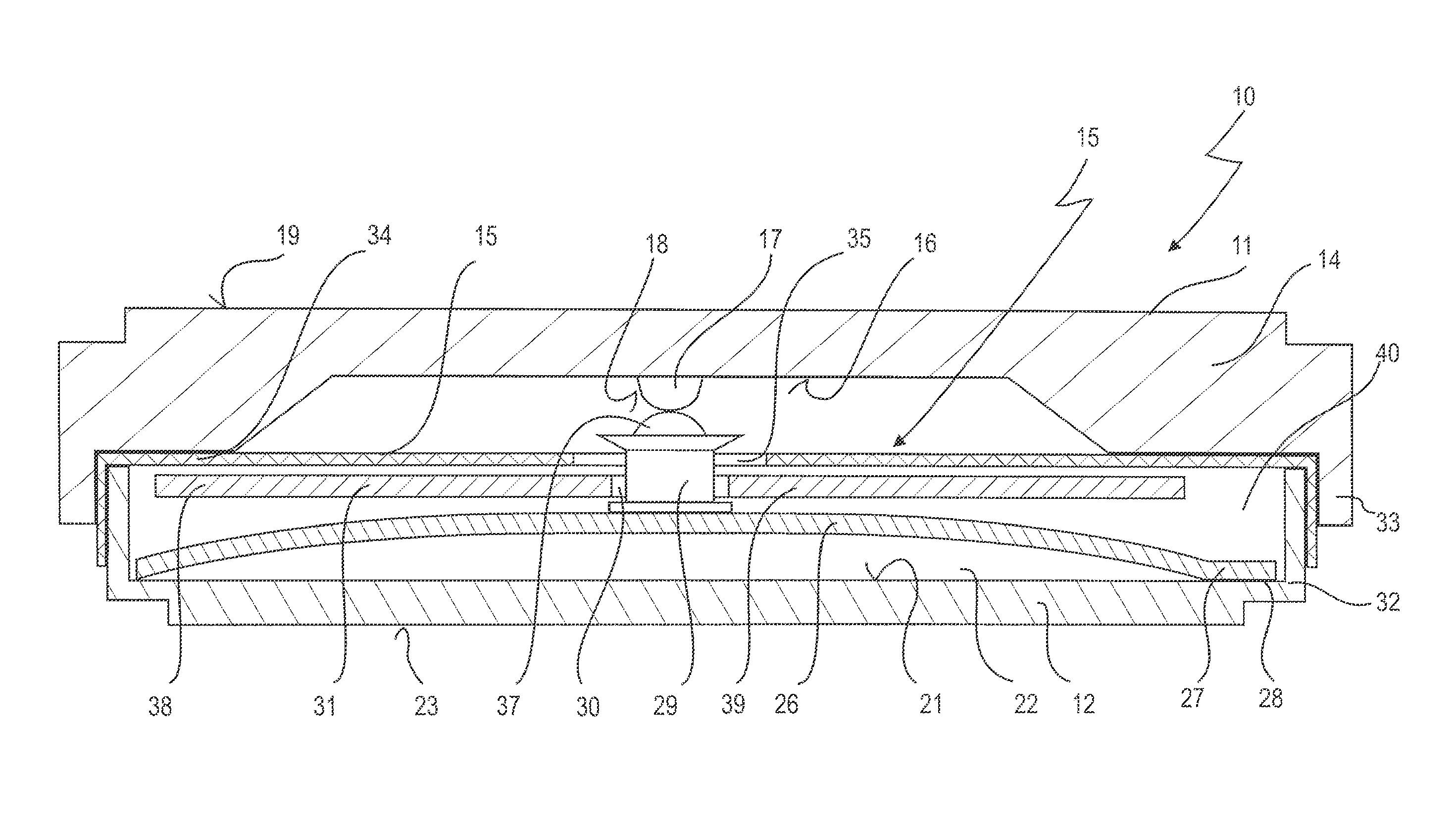
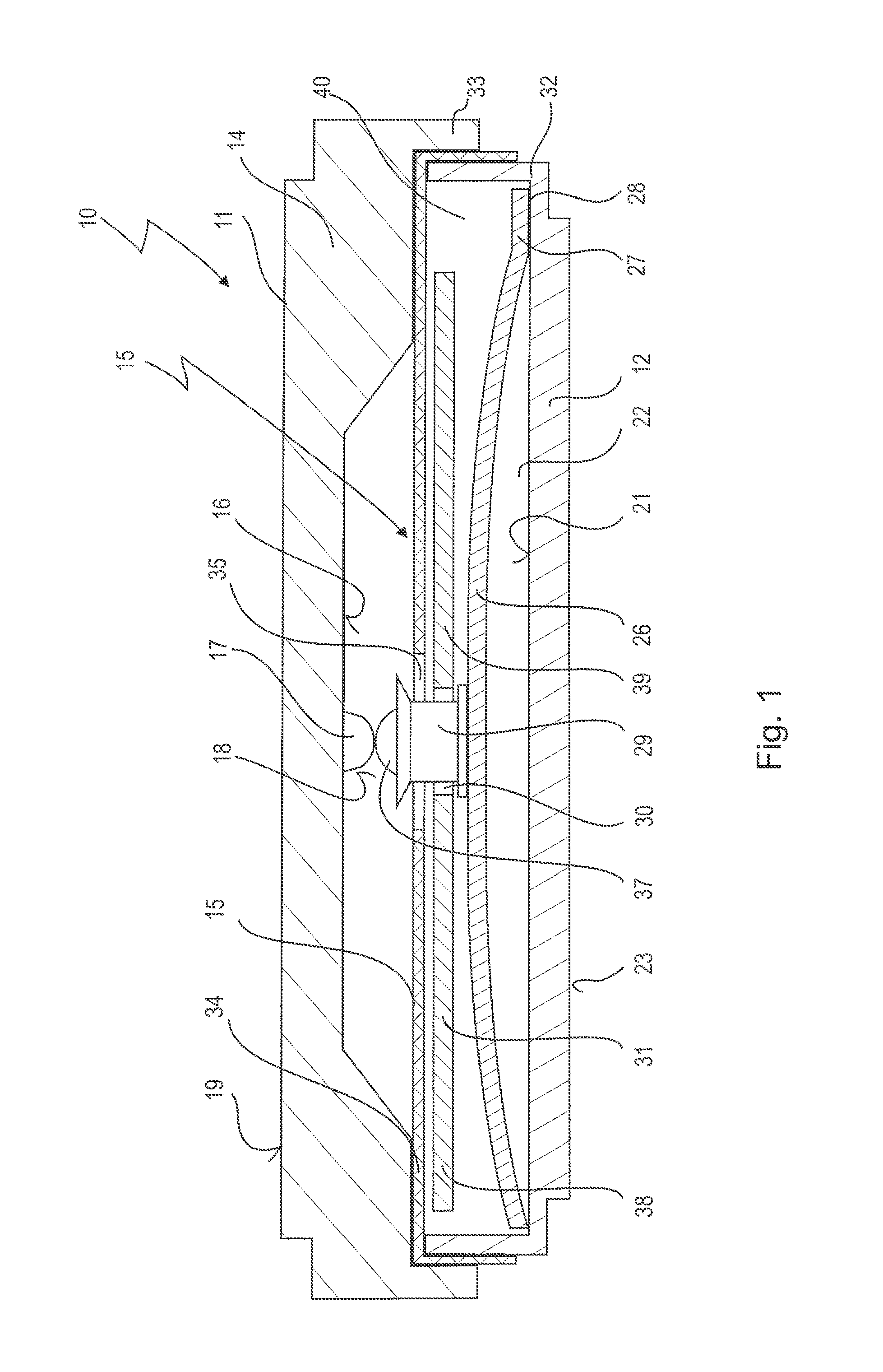
[0105]FIG. 1 shows at 10 a temperature-dependent switch comprising a housing 11, which comprises a lower part 12 produced from electrically conductive material and an upper part 14 produced from electrically conductive material.

[0106]An insulating film 15 is arranged between upper part 14 and lower part 12, and electrically insulates the upper part 14 from the lower part 12

[0107]A fixed contact block 17 is arranged on the upper part 14 on the inner side 16 thereof, said contact block having a first contact area 18 facing towards the lower part 12.

[0108]The contact block 17 is thus electrically connected to the upper part 14, such that the outer side thereof is available as a first external connection 19.

[0109]The lower part 12 has a second contact area 22 on its inner side 21. Since the lower part 12 is likewise electrically conductive, its outer side serves as a second external connection 23.

[0110]A temperature-dependent switching mechanism 25 is arranged in the housing 11, which s...


PUM


Abstract

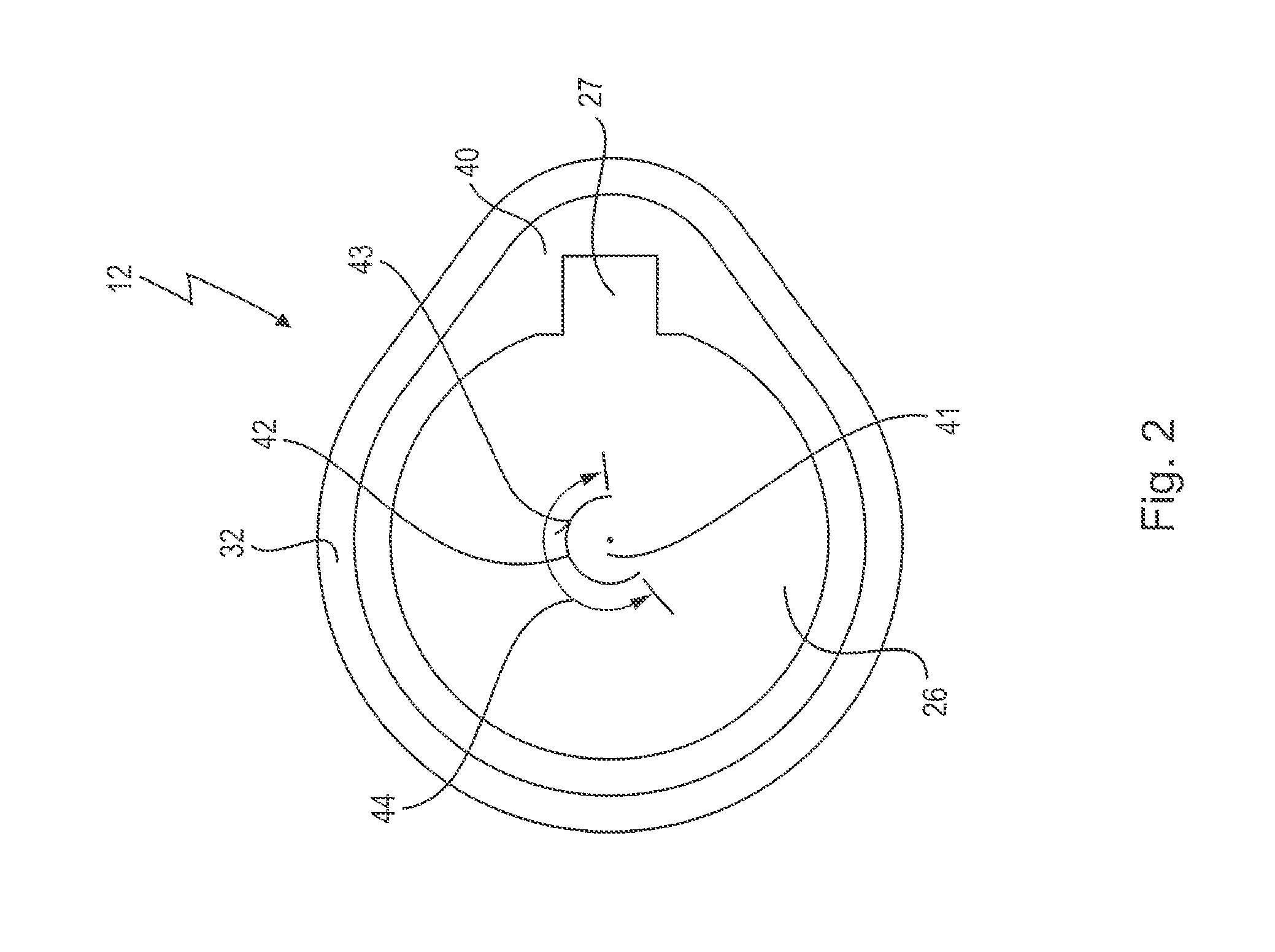
A temperature-dependent switching mechanism for use with a temperature-dependent switch with a first and a second external connection, has a snap-action disc with a bearing region on which a movable contact part is captively held, wherein the contact part interacts with the first contact area and the snap-action disc interacts with the second contact area, the bearing region being separated from the snap-action disc by a gap extending over more than 180° of its circumferential region.

Description

CROSS-REFERENCE TO RELATED APPLICATIONS[0001]This is the national stage of international patent application PCT / EP2012 / 073066, filed Nov. 20, 2012 and designating the United States, which was published in German as WO 2013 / 076059 A1, and claims priority to German patent application DE 10 2011 119 637.8, filed Nov. 22, 2011, which is incorporated herein by reference.BACKGROUND OF THE INVENTION[0002]1. Field of the Invention[0003]The present invention relates to a temperature-dependent switching mechanism for a temperature-dependent switch, wherein the switching mechanism comprises a snap-action disc, on which is provided a bearing region on which a movable contact part is captively held, wherein with the switching mechanism mounted in said switch the contact part interacts with a first contact area and the snap-action disc interacts with a second contact area of said switch such that the snap-action disc lifts the movable contact part off from the first contact area depending on its ...

Claims


Application Information

Patent Timeline
Patent Type & Authority Applications(United States)
IPC IPC(8): H01H37/54
CPCH01H37/54H01H37/52H01H37/5427H01H2037/525H01H2037/5472H01H2037/5481H01H2037/549
Inventor HOFSAESS, MARCEL P.
Owner HOFSAESS MARCEL P
Learn More