Terminal crimping machine with a terminal feed alignment aid

Active Publication Date: 2014-11-13
TYCO ELECTRONICS LOGISTICS AG (CH)
View PDF10 Cites 21 Cited by
  • Summary
  • Abstract
  • Description
  • Claims
  • Application Information

AI Technical Summary

Benefits of technology

The patent text describes a machine and method for crimping terminals to wires. The machine includes an applicator with a movable ram and an anvil, and an image acquisition device to capture images of the crimping zone. A display device shows the captured images, and an alignment module can be used to align the terminal with the anvil using the displayed images. The technical effect of this invention is that it allows for easier and more precise alignment of terminals during crimping, which improves the quality and efficiency of the crimping process.

Problems solved by technology

A terminal that is not properly located in either the side-to-side or front-to-back directions will not meet the crimp specification after it is crimped to a wire.
One area of difficulty is adjusting the side-to-side feed position, which is especially difficult with physically small terminals.
In addition to requiring skill and diligence, these small manual adjustments take time and reduce production efficiency.
Costs are increased due to reduced efficiency and discarded misaligned leads.
There is a lack of gages or setup tools to help the operator with this task.

Method used


Image

  • Terminal crimping machine with a terminal feed alignment aid
  • Terminal crimping machine with a terminal feed alignment aid
  • Terminal crimping machine with a terminal feed alignment aid

Examples


Embodiment Construction

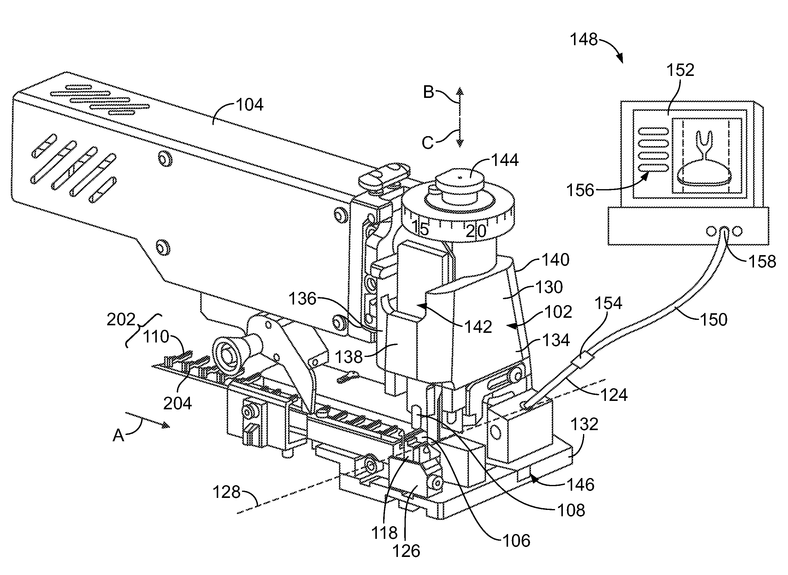
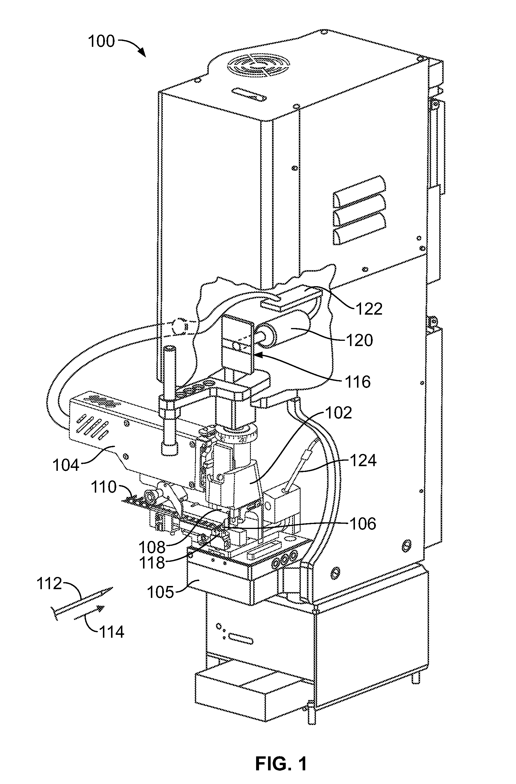
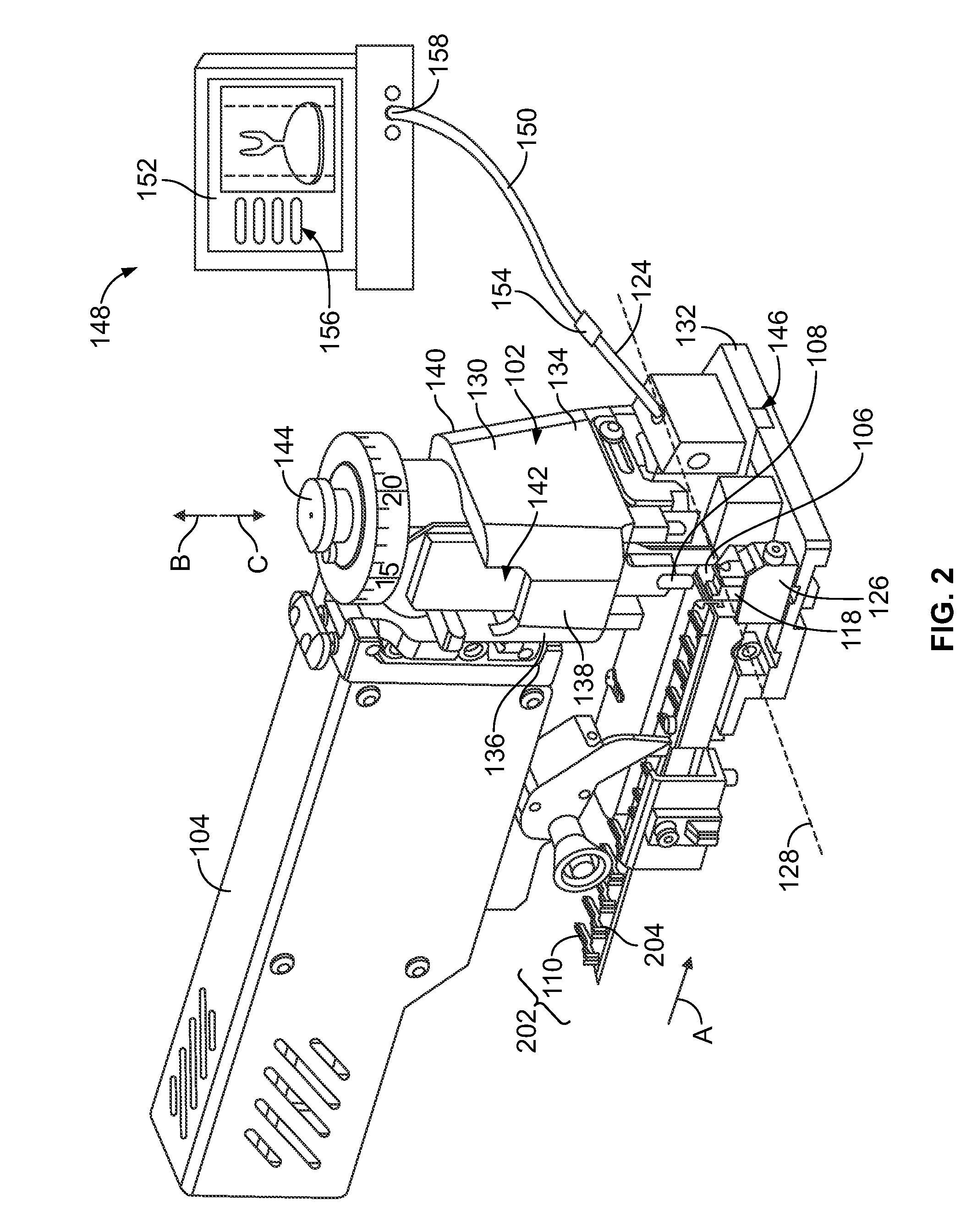
[0020]FIG. 1 is a perspective view of a crimping machine 100 having an applicator 102 and a feeder device 104. The crimping machine 100 is illustrated as a terminal crimping machine used for crimping connectors to wires, however, other types of machines may be used, such as an insulation displacement connector (IDC) machine, a welding machine, and the like, that attach connectors to wires using processes other than crimping. Alternatively, the crimping machine 100 may be another type of crimping machine such as a lead frame machine.

[0021]The applicator 102 is coupled to a support 105 of the crimping machine 100. The applicator 102 may be removed and replaced with a different applicator, such as when the applicator 102 is worn or damaged or when an applicator having a different configuration is desired. The applicator 102 has a terminating zone or crimping zone 106 and includes a crimper or crimp tooling 108 and an anvil 118 as the mechanical tooling for crimping electrical connector...


PUM


Abstract

A terminal crimping machine includes an applicator having a movable ram and an anvil. The anvil is located in a crimping zone and configured to receive a terminal thereon. The ram has crimp tooling that is configured to crimp the terminal on the anvil to a wire during a crimp stroke of the ram. An image acquisition device is positioned to acquire at least one image of the crimping zone. A display device is configured to display the at least one acquired image.

Description

BACKGROUND OF THE INVENTION[0001]The subject matter herein relates generally to terminal feed alignment aids for terminal crimping machines.[0002]Electrical terminals are typically crimped onto wires by a crimping machine to form a lead. In operation, a terminal is placed in a crimp zone, and an end of a wire is inserted into the ferrule or barrel of the terminal. A ram is caused to move toward the base through a crimp stroke, thereby crimping the terminal onto the wire. The terminals, prior to crimping, are typically provided in strip form. The strip of terminals must be manually loaded into the crimping machine by an operator. The position of the terminal strip within the crimp zone is critical to the overall performance. A terminal that is not properly located in either the side-to-side or front-to-back directions will not meet the crimp specification after it is crimped to a wire. Leads that do not meet crimp specifications are discarded.[0003]There are several mechanical adjust...

Claims


Application Information

Patent Timeline
IPC IPC(8): H01R43/058H01R43/048
CPCH01R43/058H01R43/048H01R43/055Y10T29/49185Y10T29/53235
Inventor NICHOLAS, KEITH LYNNSNYDER, JAY ALAN
Owner TYCO ELECTRONICS LOGISTICS AG (CH)
Why Eureka
Try Eureka