
Imaging apparatus, control method, and storage medium

a technology of imaging apparatus and control method, applied in the field of imaging apparatus, can solve the problem of more difficult to suppress the influence of flicker

Active Publication Date: 2014-11-13
CANON KK
View PDF10 Cites 16 Cited by
  • Summary
  • Abstract
  • Description
  • Claims
  • Application Information

AI Technical Summary

Benefits of technology

The present invention relates to an imaging apparatus that can automatically determine the optimal exposure timing for a subject based on the amount of light measured from the subject. The apparatus has two modes: a first mode where the exposure timing is determined based on the timing calculated after the light metering unit performs multiple light metering, and a second mode where the exposure timing is determined based on the timing calculated after the light metering unit performs additional light metering. The second mode has a smaller number of times compared to the first mode. This feature allows for more precise and accurate exposure timing, resulting in improved image quality.

Problems solved by technology

Therefore, in the technique discussed in Japanese Patent Application Laid-Open No. 2006-222935, the later the time when the image is captured in the capturing of the plurality of images is, the more easily the peak timing obtained from the detection result deviates from the actual peak timing, and the more difficult it becomes to suppress an influence of the flicker.

Method used


Image

  • Imaging apparatus, control method, and storage medium
  • Imaging apparatus, control method, and storage medium
  • Imaging apparatus, control method, and storage medium

Examples


Embodiment Construction

[0022]Various exemplary embodiments, features, and aspects of the invention will be described in detail below with reference to the drawings.

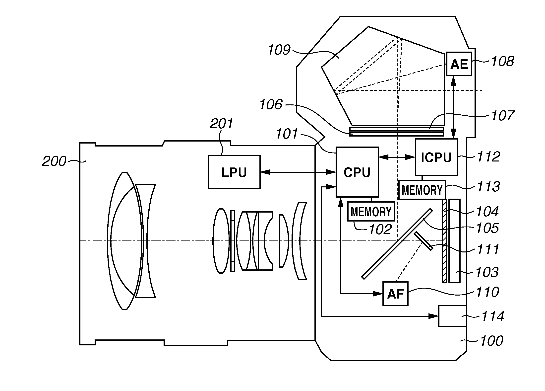
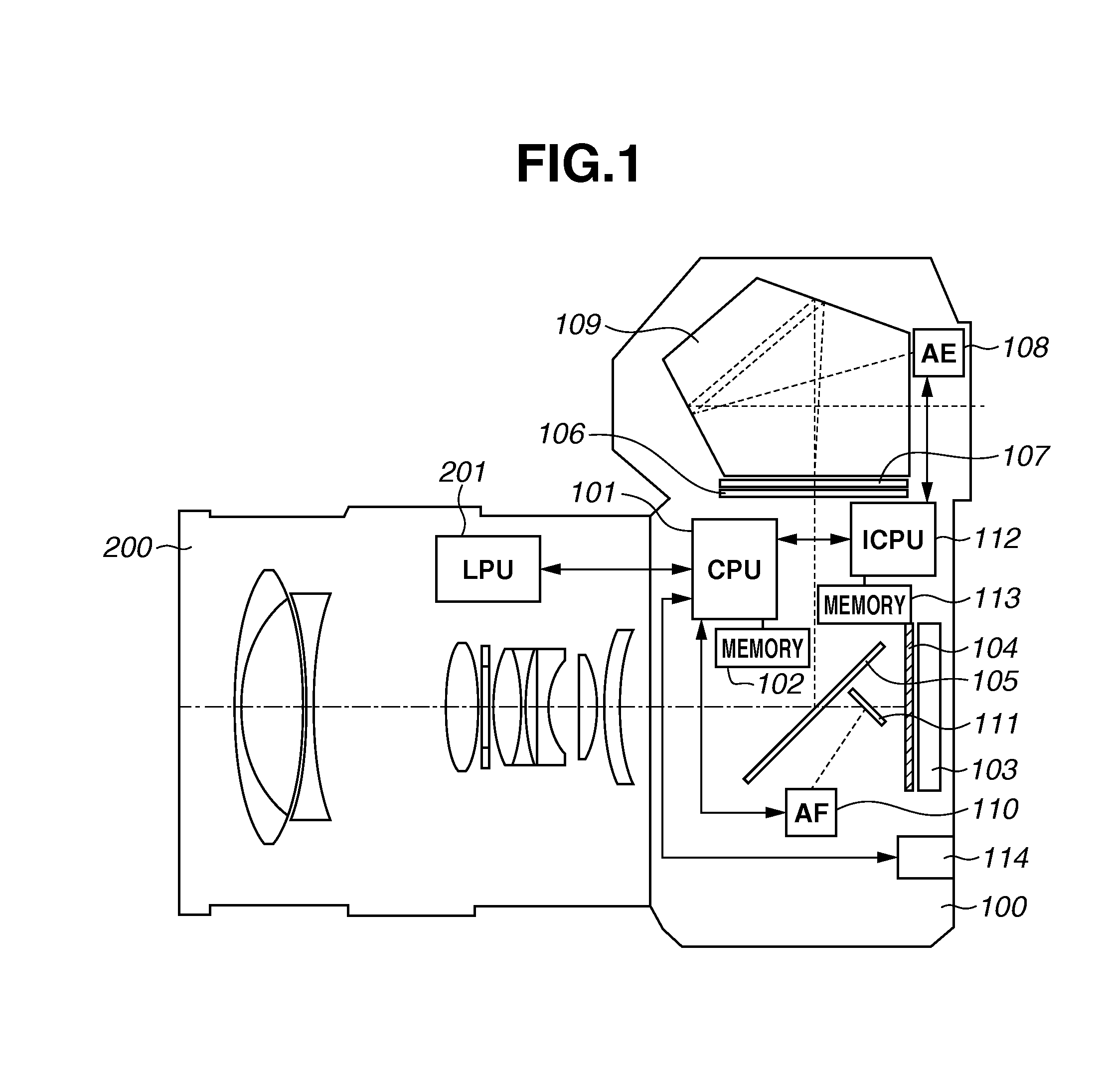
[0023]FIG. 1 is a schematic view illustrating a configuration of an imaging apparatus according to an exemplary embodiment. The imaging apparatus according to the present exemplary embodiment includes a camera body 100 and a lens unit 200 detachably attached to the camera body 100.

[0024]A configuration of the camera body 100 will be described below. A microcomputer central processing unit (CPU) (hereinafter referred to as a camera microcomputer) 101 controls each unit in the camera body 100. A memory 102 is a memory such as a random access memory (RAM) or a read-only memory (ROM) connected to the camera microcomputer 101.

[0025]An image sensor 103 is an image sensor such as a charge coupled device (CCD) sensor or a complementary metal oxide semiconductor (CMOS) sensor including an infrared cut filter and a low-pass filter, and photoelectrically ...


PUM


Abstract

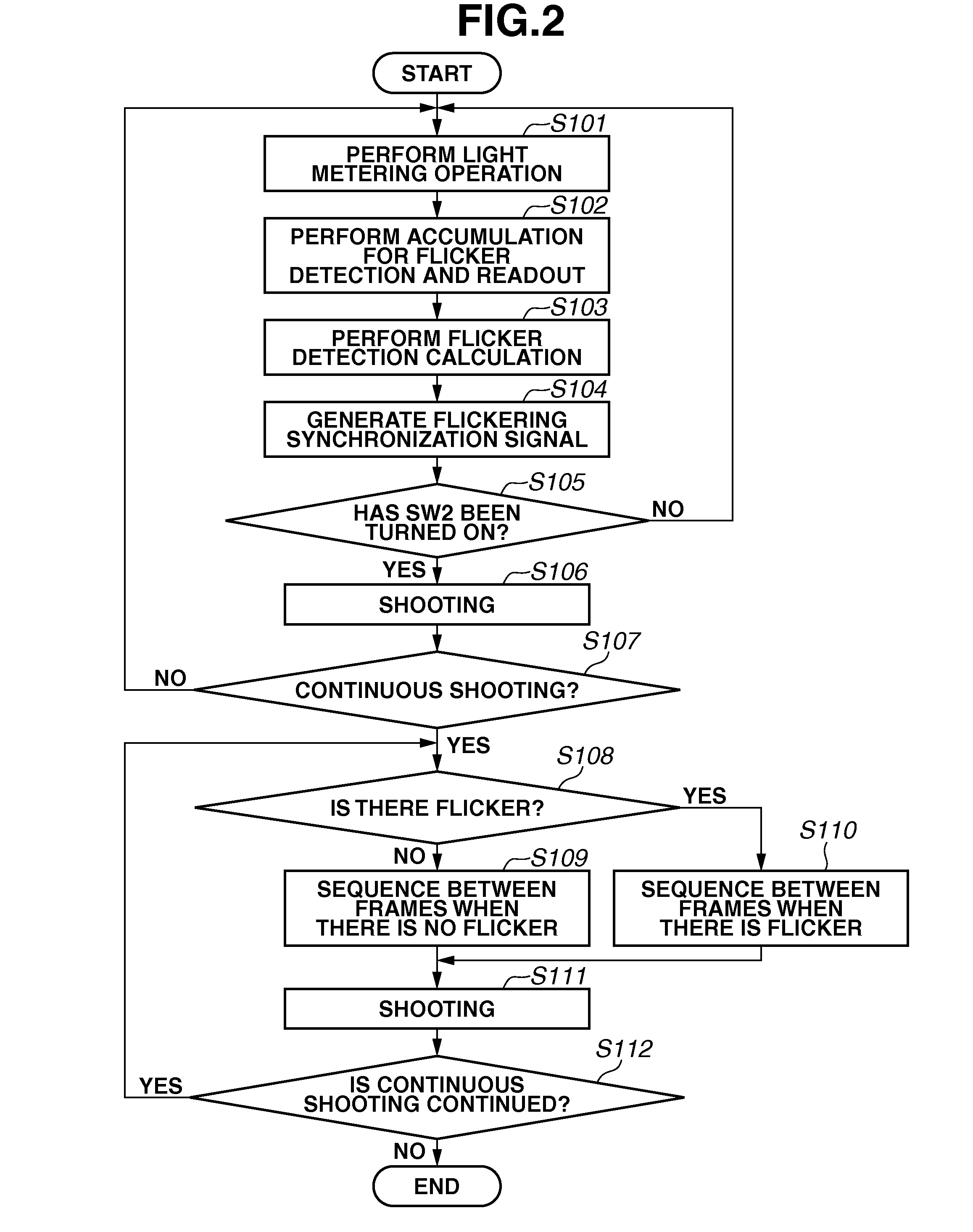
An imaging apparatus has a first mode in which a determination unit determines an exposure timing of an imaging unit based on a timing calculated by a calculation unit after a light metering unit performs light metering a first number of times, and a second mode in which the determination unit determines the exposure timing of the imaging unit based on the timing calculated by the calculation unit after the light metering unit performs the light metering a second number of times.

Description

BACKGROUND OF THE INVENTION[0001]1. Field of the Invention[0002]The present invention relates to an imaging apparatus, and more particularly, a technique for suppressing an influence of flicker generated under an artificial light source such as a fluorescent lamp.[0003]2. Description of the Related Art[0004]In recent years, the sensitivity of an imaging apparatus such as a digital camera or a mobile phone camera has been becoming higher. Therefore, a bright image with suppressed blur can be acquired by shooting with a high shutter speed (i.e., with a short exposure time) even under a relatively dark environment such as an indoor environment.[0005]In the case of a fluorescent lamp, which is commonly used as an indoor light source, there occurs flicker known as a phenomenon that illumination light periodically fluctuates due to an influence of a commercial power supply frequency. When shooting with a high shutter speed under a light source that causes such flicker (hereinafter referre...

Claims


Application Information

Patent Timeline
IPC IPC(8): H04N5/235
CPCH04N5/2353H04N23/745H04N23/73H04N23/70
Inventor NAKAGAWARA, NAOYUKI
Owner CANON KK
Learn More