
Keyswitch device and keyboard

a key switch and keyboard technology, applied in the direction of contact mechanisms, interspersed finger contacts, emergency contacts, etc., can solve the problems of two contact pairs not being stably connected, keytops no longer being able to smoothly move, and keytops not being suitabl

Active Publication Date: 2014-11-20
FUJITSU COMPONENENT LTD
View PDF12 Cites 10 Cited by
  • Summary
  • Abstract
  • Description
  • Claims
  • Application Information

AI Technical Summary

Benefits of technology

The patent text relates to a keyswitch device and a keyboard that includes the keyswitch device. The technical effect of this invention is to provide a keyswitch device with improved durability and reliability.

Problems solved by technology

When a member is arranged for guiding the keytop by sliding, if foreign matter enters the keyswitch device, the keytop will no longer be able to smoothly move.
In such a keyswitch device which simultaneously connects two contact pairs, there was the problem that the above such mechanism which is provided with a disc spring or mechanism which uses a rubber cup to support the keytop was not suitable.
For example, in a mechanism which uses a rubber cup to support the keytop, if pushing a position which deviates from the center of the keytop, the keytop would end up tilting, so sometimes the two contact pairs cannot be stably connected.

Method used


Image

  • Keyswitch device and keyboard
  • Keyswitch device and keyboard
  • Keyswitch device and keyboard

Examples


Embodiment Construction

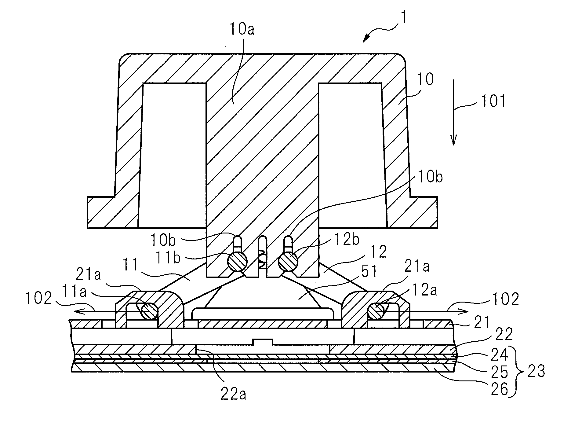
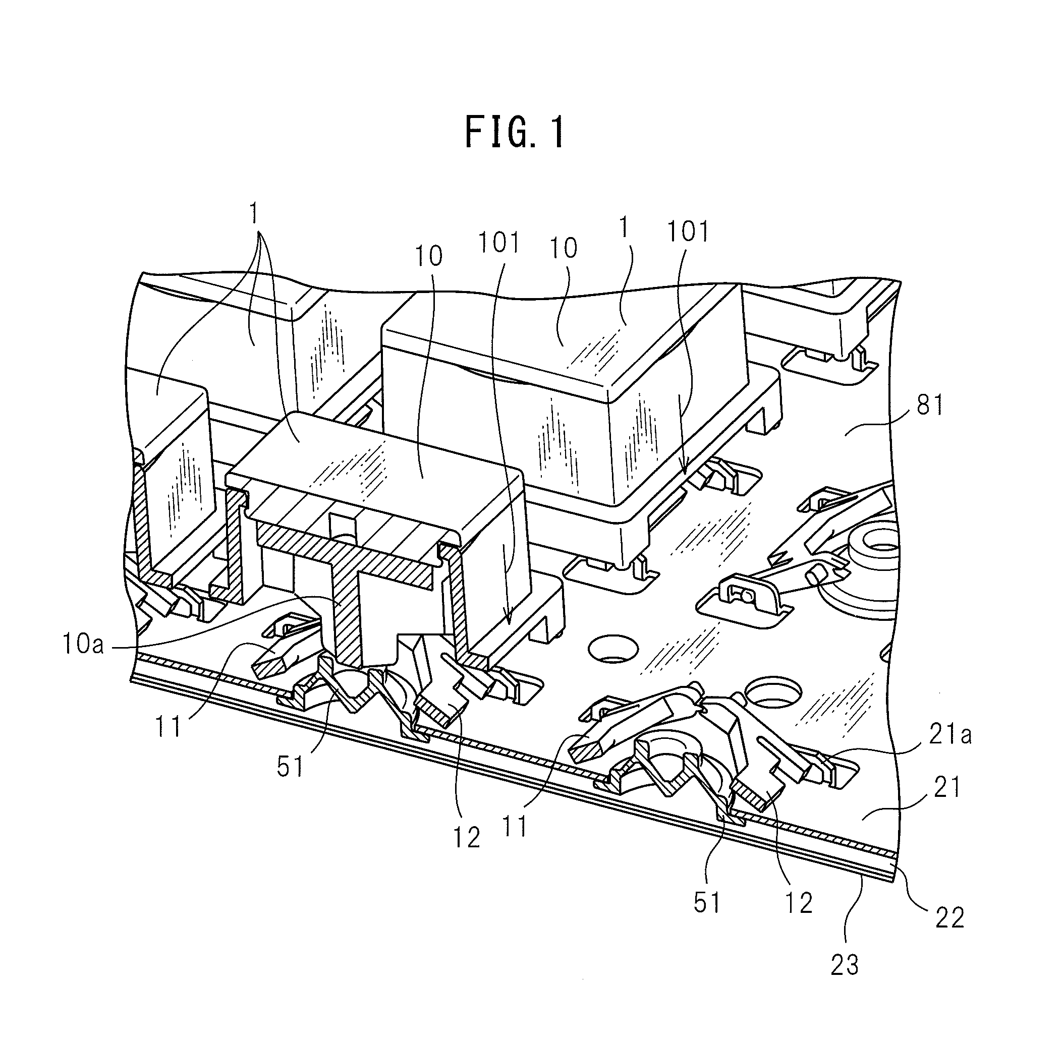
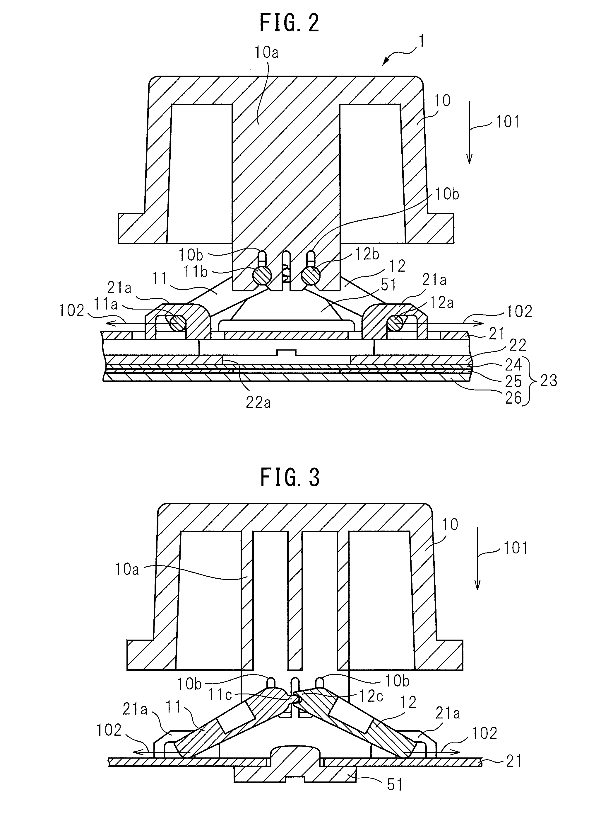
[0037]Referring to FIG. 1 to FIG. 22, a keyswitch device and keyboard of an embodiment will be explained. In the present embodiment, a keyswitch device which is arranged at the keyboard is explained as an example.

[0038]FIG. 1 is a perspective view of the keyboard in the present embodiment when cutting along its part. FIG. 1 shows the state where a cover member etc. at the surface of the keyboard is detached and keytops 10 are detached from some of the keyswitch devices 1. The keyboard 81 in the present embodiment includes a plurality of keyswitch devices 1. The plurality of keyswitch devices 1 are arranged aligned. The keyboard 81 in the present embodiment has a base member 21. The base member 21 in the present embodiment has the plurality of keyswitch devices 1 attached to it.

[0039]FIG. 2 is a cross-sectional view of a keyswitch device in the present embodiment. The keyswitch device 1 shown in FIG. 1 and FIG. 2 is provided with a keytop 10 functions as a moving member which moves w...


PUM


Abstract

A keyswitch device which is provided with a support mechanism which supports a keytop in a movable manner, and a membrane sheet which has a plurality of upper electrodes and a plurality of lower electrodes which respectively correspond to the plurality of the upper electrodes and which form contact pairs with the corresponding upper electrodes. A plurality of contact pairs are arranged for a single keytop. The rubber cup pushes the plurality of contact pairs which are arranged for the single keytop.

Description

CROSS-REFERENCE TO RELATED APPLICATIONS[0001]This application is based upon and claims the benefit of priority of the prior Japanese Patent Application No. 2013-102410, filed May 14, 2013, the entire contents of which are incorporated herein by reference.BACKGROUND OF THE INVENTION[0002]1. Field of the Invention[0003]The present invention relates to a keyswitch device and to a keyboard which is provided with the keyswitch device.[0004]2. Description of the Related Art[0005]A keyswitch device is used in control panels, etc., of industrial machinery for inputting predetermined information to a main apparatus. Alternatively, a keyboard which is provided with a plurality of keyswitch devices is used. In a keyboard, keyswitch devices are arranged for specific predetermined information. On the surfaces of each keytop, a letter to be input or control content or other input information is engraved. When a keytop is pushed, a key input signal which corresponds to the input information which ...

Claims


Application Information

Patent Timeline
Patent Type & Authority Applications(United States)
IPC IPC(8): H01H13/02H01H13/70
CPCH01H13/02H01H13/70H01H3/125H01H13/79H01H13/807H01H2203/02H01H2203/038H01H2203/054H01H2215/006
Inventor OHTSUKA, HIROMITAGA, DAISUKESAITOU, TAKUYANAKAHARA, MOMOSUKE
Owner FUJITSU COMPONENENT LTD
Learn More