Rotor Assembly with Electron Beam Welded End Caps

a technology of electron beam welding and rotor assembly, which is applied in the direction of synchronous motors, dynamo-electric machines, electrical apparatus, etc., can solve the problems of cost and complexity of fabrication/assembly

Inactive Publication Date: 2014-11-20
TESLA INC
View PDF9 Cites 24 Cited by
  • Summary
  • Abstract
  • Description
  • Claims
  • Application Information

AI Technical Summary

Problems solved by technology

Typically these techniques make trade-offs between several, often competing, factors that include (i) maximizing the electrical conductivity between the rotor bars; (ii) rotor w...

Method used


Image

  • Rotor Assembly with Electron Beam Welded End Caps
  • Rotor Assembly with Electron Beam Welded End Caps
  • Rotor Assembly with Electron Beam Welded End Caps

Examples


Embodiment Construction

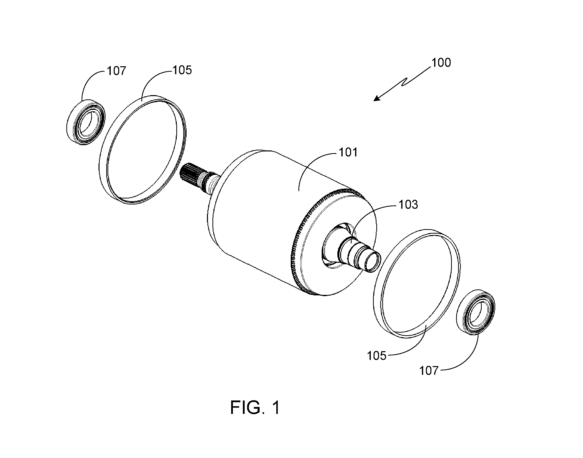
[0027]FIG. 1 is a partially exploded, perspective view of the primary components of a rotor assembly 100 in accordance with a preferred embodiment of the invention. It will be appreciated that other configurations may be used with the invention, and the specific designs and dimensions provided relative to the preferred embodiment are only meant to illustrate, not limit, the scope of the invention and should not be considered to be to scale. Additionally, it should be understood that identical element symbols used on multiple figures refer to the same component, or components of equal functionality.

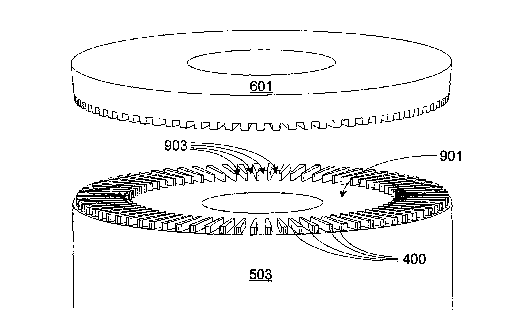
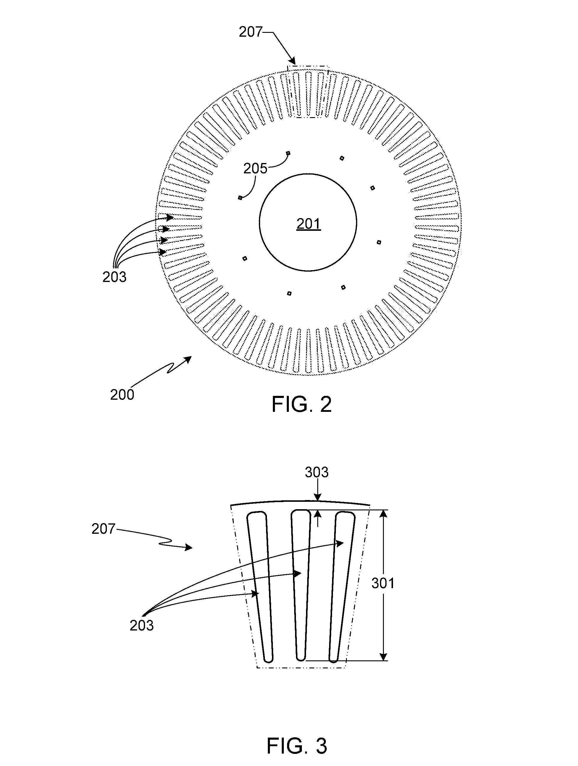
[0028]As described in further detail below, the core assembly 101 is comprised of a plurality of laminated discs, typically referred to as the rotor stack, and a plurality of conductor bars, also referred to herein as rotor bars. Core assembly 101 is coaxially mounted to a rotor shaft 103, shown already inserted into assembly 101 in this figure. Shaft 103 may include keys or similar means ...


PUM


Abstract

A rotor assembly and a method for fabricating the same are provided in which a pair of end caps, positioned at either end of the stack of laminated discs, are fusion welded to the rotor bars using an electron beam welder, thereby yielding improved electrical and mechanical characteristics in a low weight assembly.

Description

FIELD OF THE INVENTION[0001]The present invention relates generally to electric motors and, more specifically, to an electric motor rotor assembly.BACKGROUND OF THE INVENTION[0002]AC induction motors are widely used in a variety of industrial and residential applications. In general, this type of motor includes a laminated magnetic core mounted to a drive shaft. The laminated magnetic core may be fabricated from a plurality of laminated magnetic discs, or from a plurality of arc-like core segments. The laminated magnetic core includes a plurality of longitudinal slots into which bars of electrically conductive metal are fit. The ends of the bars extend beyond either end of the laminated magnetic core. An end-ring or end cap at either end of the laminated magnetic core is used to mechanically and electrically join the ends of the rotor bars.[0003]It will be appreciated that there are numerous techniques that may be used to fabricate the rotor assembly in general and the cap assembly ...

Claims


Application Information

Patent Timeline
IPC IPC(8): H02K17/16
CPCH02K17/16H02K17/165H02K15/0012H02K17/20H02K17/18
Inventor NELSON, DAVID FREDLUAN, SHYI-PERNG PHILLIPPEARCE, JR., EDWIN MARCUMFONG, WILLIAM RANDALL
Owner TESLA INC
Why Eureka
Try Eureka