
Steel pipe socket and method of connecting steel pipe pile and steel pipe column using the same

Active Publication Date: 2014-12-04
RES INST OF IND SCI & TECH +1
View PDF3 Cites 9 Cited by
  • Summary
  • Abstract
  • Description
  • Claims
  • Application Information

AI Technical Summary

Benefits of technology

The present invention provides a steel pipe socket for connecting steel pipes without the need for poupping concrete to form a concrete bottom plate. This reduces construction periods and costs. Additionally, a horizontality maintaining member is included to ensure verticality of the steel pipe column mounted on the steel pipe pile. This achieves improved stability and load bearing capacity.

Problems solved by technology

It is very difficult to perform work for directly installing a steel pipe column on an installed steel pipe pile.
The reason is that eccentricity in a horizontal direction may occur due to an installation error at a position where the steel pipe pile or the steel pipe column is installed, and in a case in which a predetermined value of inclination occurs when the steel pipe pile is installed in a construction site, it is very difficult to ensure verticality of the steel pipe column that is mounted on the steel pipe pile.
The method of connecting the steel pipe pile and the steel pipe column using the concrete bottom plate in the related art is performed through processes of processing and assembling the iron reinforcing bars in accordance with constructing concrete foundations, installing the bottom plate bolts, installing the forms, pouring concrete, curing the concrete, installing grout, and the like, which cause a delay of a construction period and an increase in construction cost.
Particularly, in the case of plant construction that has great characteristics of fast-track construction, a significantly long construction period is required to connect a steel pipe pile and a pipe rack steel pipe column, which results in a delay in terms of plant facility commissioning.

Method used


Image

  • Steel pipe socket and method of connecting steel pipe pile and steel pipe column using the same
  • Steel pipe socket and method of connecting steel pipe pile and steel pipe column using the same
  • Steel pipe socket and method of connecting steel pipe pile and steel pipe column using the same

Examples


Embodiment Construction

Technical Problem

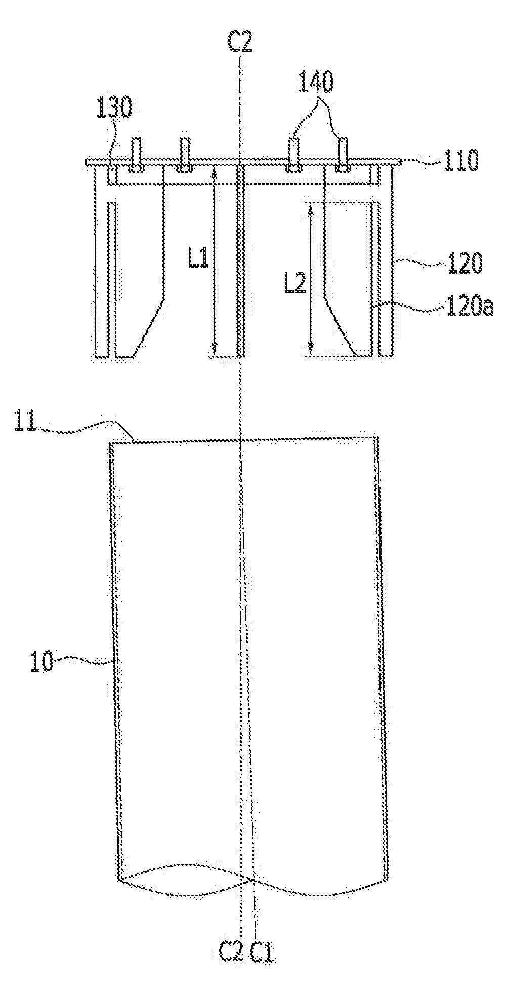
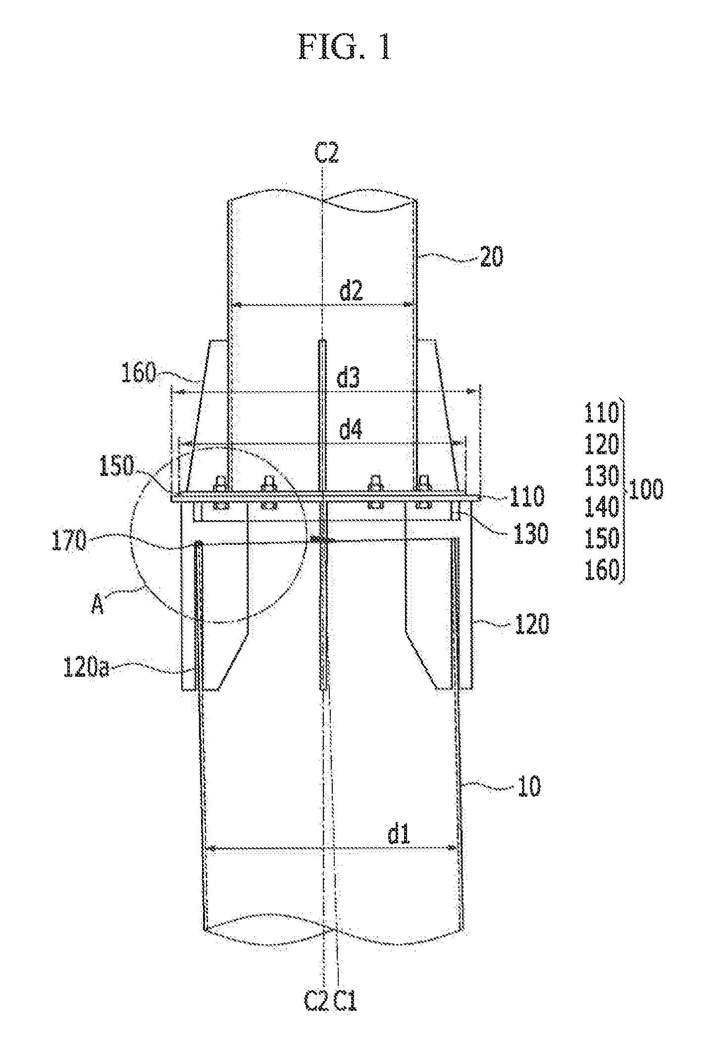
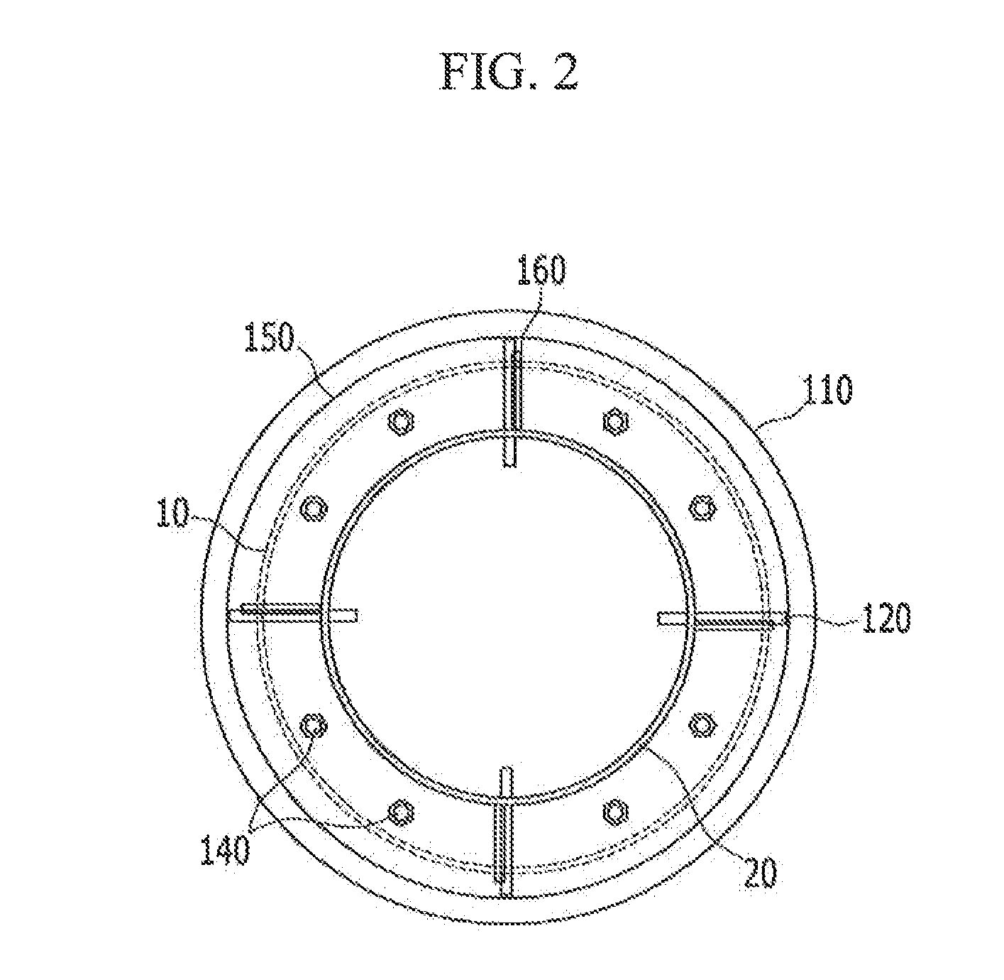
[0007]The present invention has been made in an effort to provide an economical steel pipe socket capable of simplifying a process of connecting a steel pipe pile and a steel pipe column, and shortening a construction period, and a method of connecting the steel pipe pile and the steel pipe column using the steel pipe socket.

[0008]In addition, the present invention has been made in an effort to provide a steel pipe socket capable of removing eccentricity of a steel pipe pile or a steel pipe column, and ensuring verticality of the steel pipe column, and a method of connecting the steel pipe pile and the steel pipe column using the steel pipe socket.

Technical Solution

[0009]An exemplary embodiment of the present invention provides a steel pipe socket including: a socket supporting portion which covers an upper end surface of a steel pipe pile; a plurality of socket insertion portions which are extended downward from the socket supporting portion, and have a plurality o...


PUM


Abstract

A method of connecting a steel pipe pile and a steel pipe column using a steel pipe socket according to the present invention may include: preparing the steel pipe socket including a socket supporting portion which covers an upper end surface of the steel pipe pile; inserting a plurality of socket insertion portions which are extended downward from the socket supporting portion, and have a plurality of socket grooves at a lower end portion thereof and a plurality of fastening members which are installed on the socket supporting portion; inserting the socket grooves of the steel pipe socket into an upper end portion of the steel pipe pile; mounting the steel pipe column on the socket supporting portion; and fastening the steel pipe column and the steel pipe pile using the plurality of fastening members of the socket supporting portion

Description

TECHNICAL FIELD[0001]The present invention relates to a steel pipe socket and a method of connecting a steel pipe pile and a steel pipe column using the same, and more particularly, to a steel pipe socket which connects the steel pipe pile and the steel pipe column, and a method of connecting a steel pipe pile and a steel pipe column using the same.BACKGROUND ART[0002]It is very difficult to perform work for directly installing a steel pipe column on an installed steel pipe pile. The reason is that eccentricity in a horizontal direction may occur due to an installation error at a position where the steel pipe pile or the steel pipe column is installed, and in a case in which a predetermined value of inclination occurs when the steel pipe pile is installed in a construction site, it is very difficult to ensure verticality of the steel pipe column that is mounted on the steel pipe pile.[0003]In order to remove the eccentricity of the steel pipe pile or the steel pipe column and ensure...

Claims


Application Information

Patent Timeline
IPC IPC(8): E02D5/28F16B7/04
CPCF16B7/04E02D5/285E02D5/34Y10T403/5706E02D5/24E02D5/28E02D27/12
Inventor LEE, DAE YONG
Owner RES INST OF IND SCI & TECH
Learn More