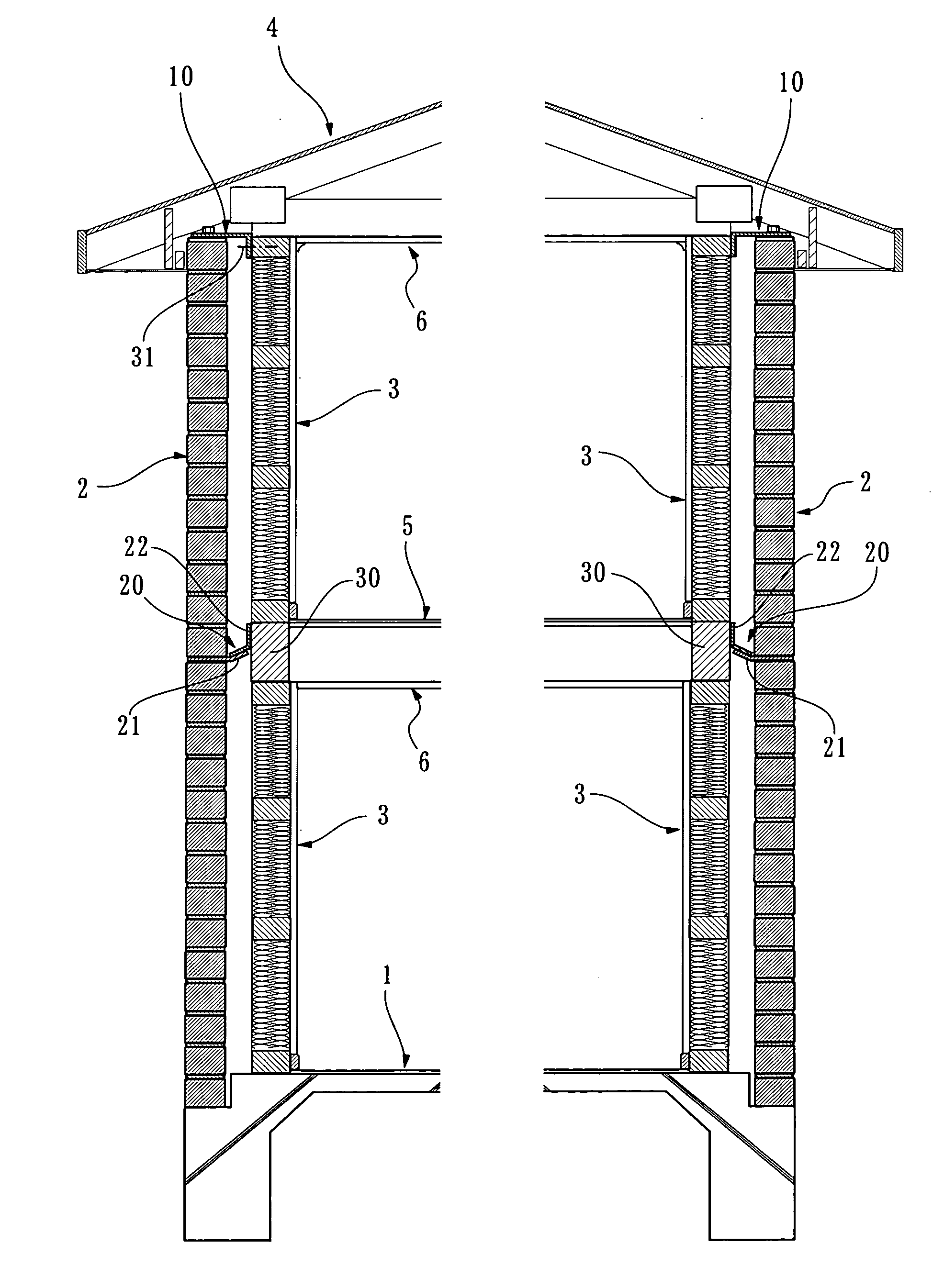
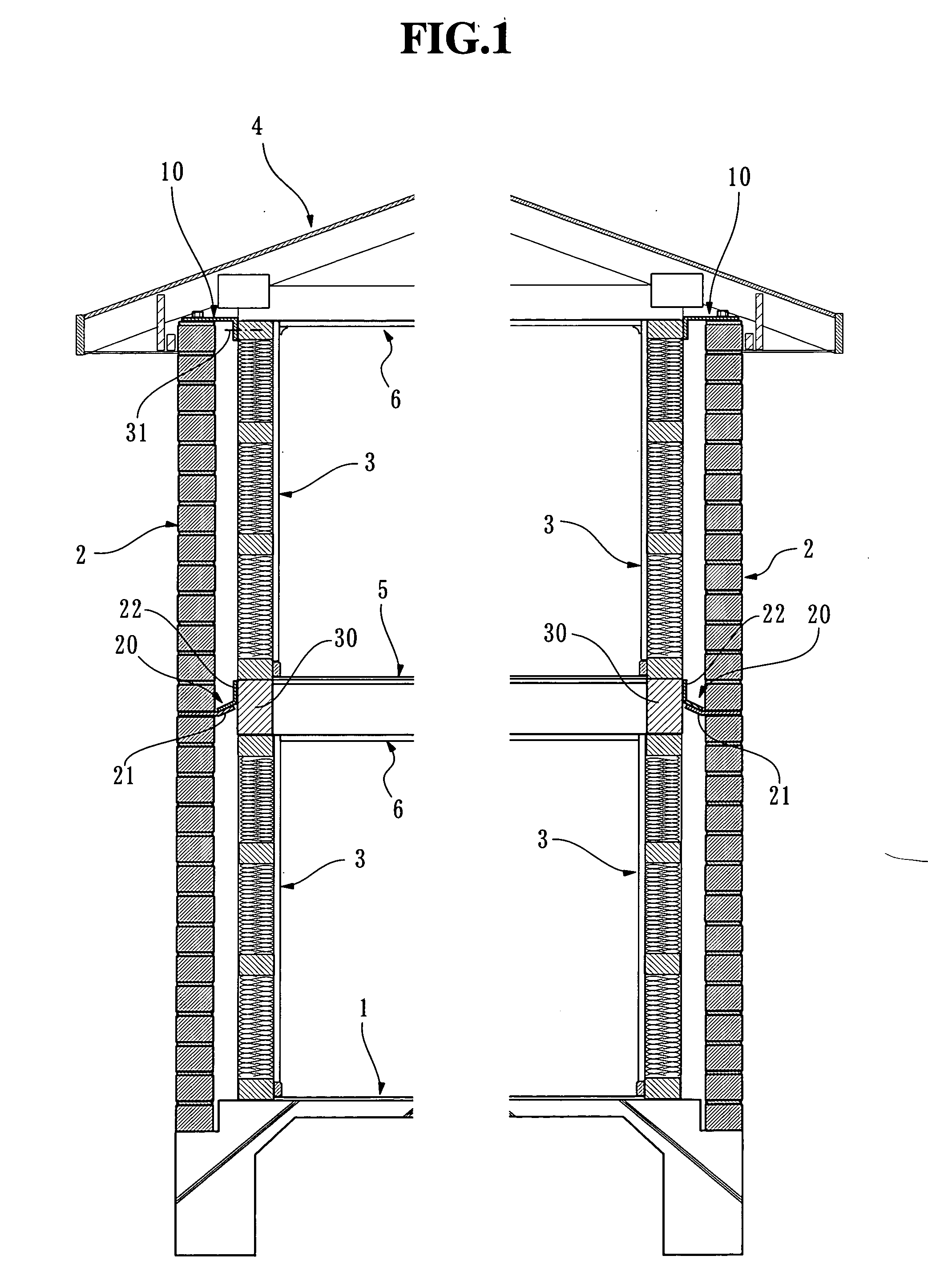
[0016] Further, according to the arrangement of the present invention, the inner walls can be constructed beforehand, and the roof can be constructed on the inner wall, and thereafter, bricklaying works for the outer walls can be performed. The bricklaying process of the outer walls is carried out under an eave of the roof, and therefore, any apprehension that the bricklaying process is delayed owing to influence of weather can be removed. In addition, since the inner walls have been already constructed before the bricklaying process of the outer walls, the bricklaying works and the interior finish works can be performed at the same time.
[0017] Furthermore, according to the aforementioned arrangement, the temporary horizontal load acting on the roof and the inner wall is transmitted to the outer wall by means of the
shear reinforcement member, and the inner wall is blocked from the wind pressure by the outer wall so that the wind pressure does not act on the inner wall. Therefore, the inner wall may have a strength that is enough to endure a permanent
vertical load such as the load of a roof, and apprehensions about problems of the resistance against earthquakes and wind can be removed with respect to the imported housing materials or the low-priced materials. Thus, it is possible to construct the inner wall with use of the imported housing materials or the low-priced materials, thereby reducing the construction costs.
[0036] According to such a construction method, the bricklaying process can be performed under the eave of the roof without being affected by rainfall. Further, the interior finish work and the bricklaying work can be carried out at the same time, whereby the construction period can be shortened.
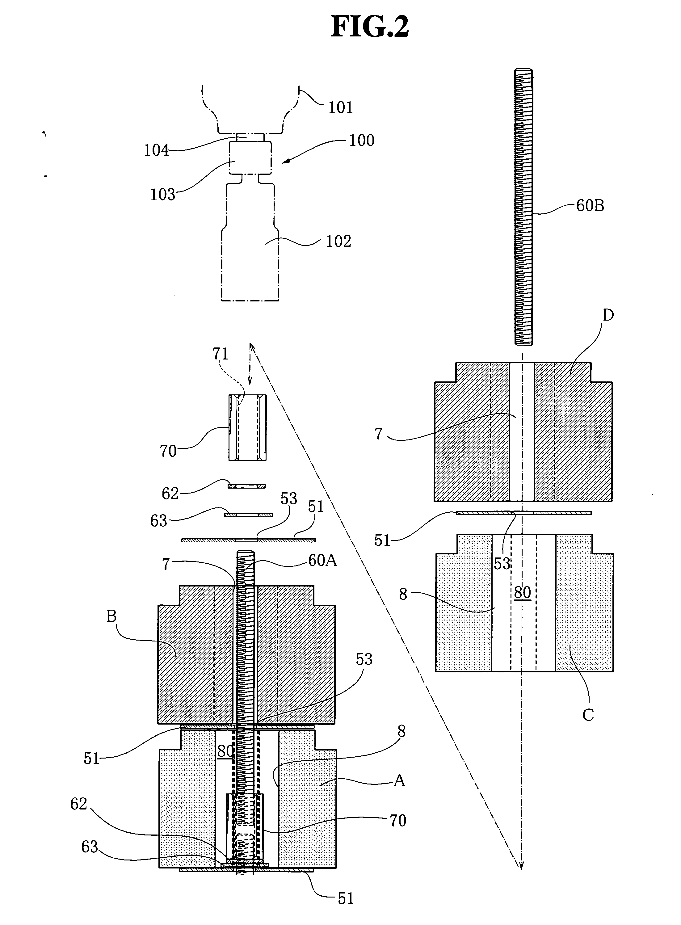
[0037] The inner wall, which has been constructed beforehand, functions as a reference or a ruler for positioning the bricks upon bricklaying, and therefore, the accuracy of bricklaying work is improved. The shear reinforcement member is fixed onto the upper face of the
brick or fixed between the bricks by tightening force of the
fastener, when the bricks are laid up to a predetermined layer. Therefore, the shear reinforcement member is fixed to the brick by the tightening force of the
fastener for the bricks, without use of any particular
fastener, fixing element, or the like, and the shear reinforcement member can be tightly fixed to the brick wall by the tightening force of the fastener.
[0038] As an application of the present invention, a construction method of a wall is provided, which improves resistance of an existing architecture against earthquakes and wind. That is, the present invention provides a method of constructing a wall of an architecture, comprising steps of:
[0041] According to such a construction method, the temporary horizontal load acting on the existing architecture is transmitted to the outer wall by the shear reinforcement member. Since the seismic force acting on the existing architecture with the outer wall thus constructed is transmitted to the brick wall by means of the shear reinforcement member, the existing architecture is improved in its resistance against earthquakes. Since the brick wall blocks the wind pressure which may otherwise act on the existing exterior wall, the existing architecture is also improved in its wind resistance. Therefore, the existing architecture, which lacks in its resistance against earthquakes and wind, is reconstructed or reinforced to have a sufficient resistance against earthquakes and wind by constructing the brick wall.

