Ophthalmic endoilluminators with directed light

a technology of ophthalmic endoilluminators and directed light, which is applied in the field of surgical instruments, can solve the problems that endoilluminators, however, may not be able to direct light in a suitable fashion

Inactive Publication Date: 2014-12-11
ALCON RES LTD
View PDF6 Cites 0 Cited by
  • Summary
  • Abstract
  • Description
  • Claims
  • Application Information

AI Technical Summary

Problems solved by technology

These endoilluminators, however, may not be able to direct light in a suitable fashion in certain situations.

Method used


Image

  • Ophthalmic endoilluminators with directed light
  • Ophthalmic endoilluminators with directed light
  • Ophthalmic endoilluminators with directed light

Examples


Embodiment Construction

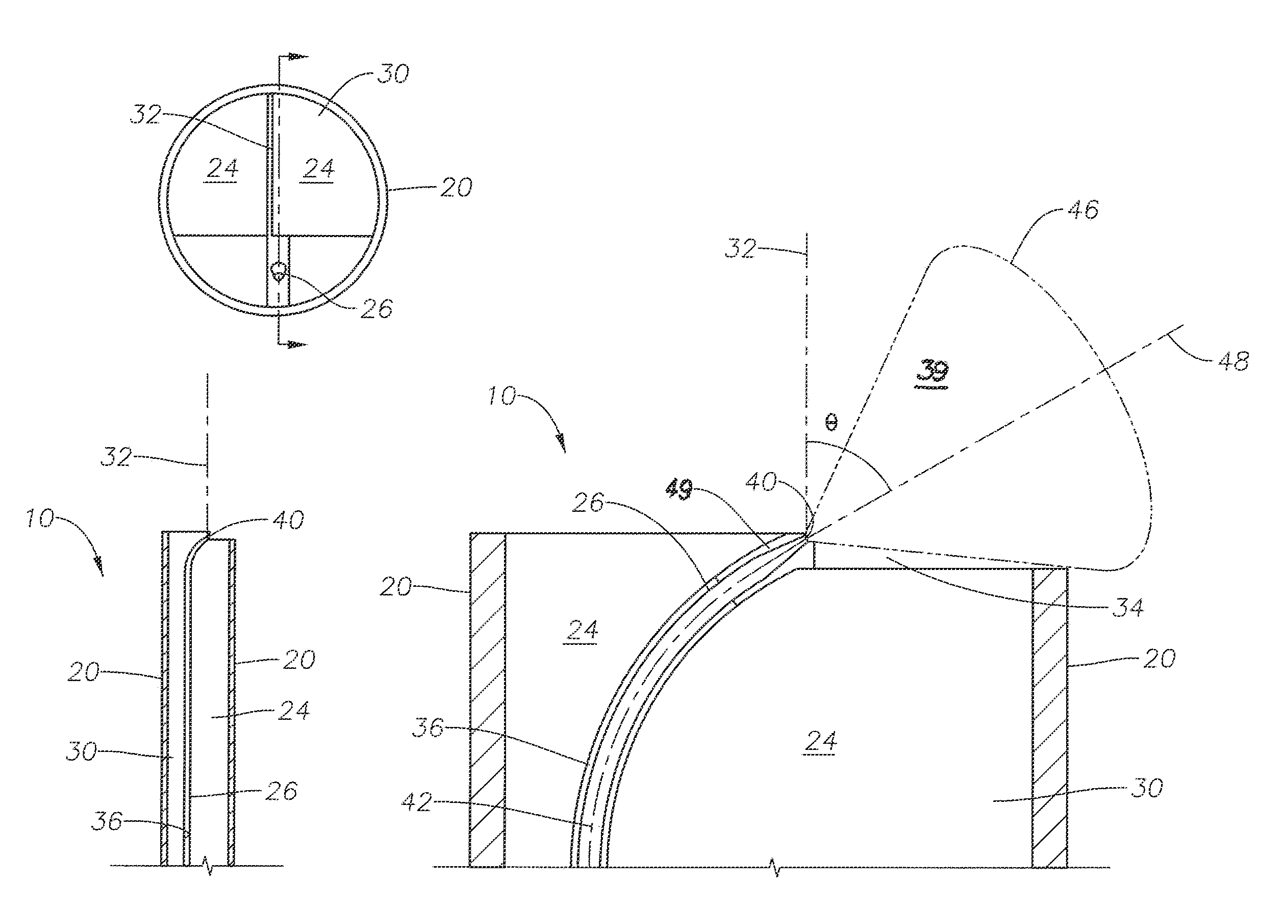
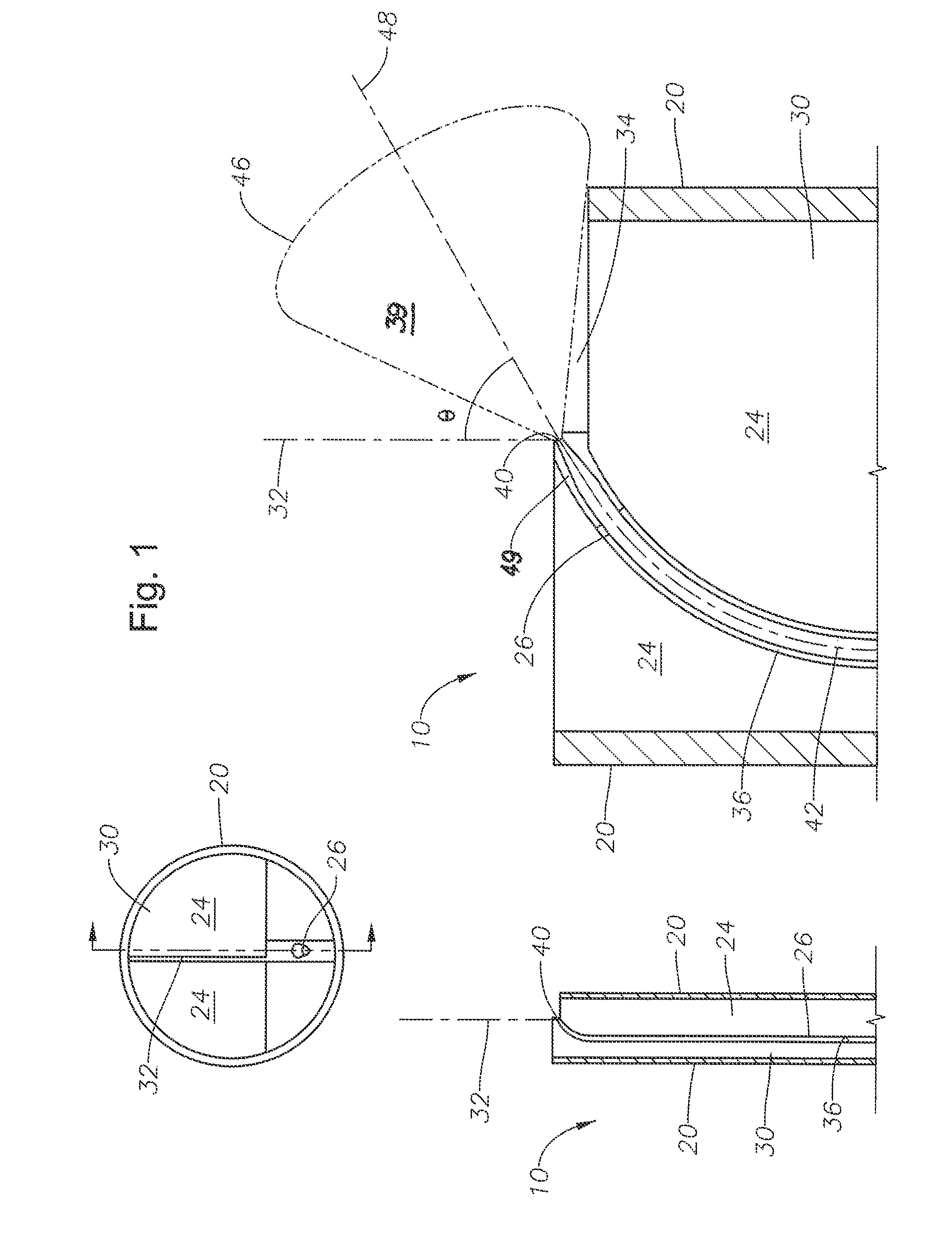
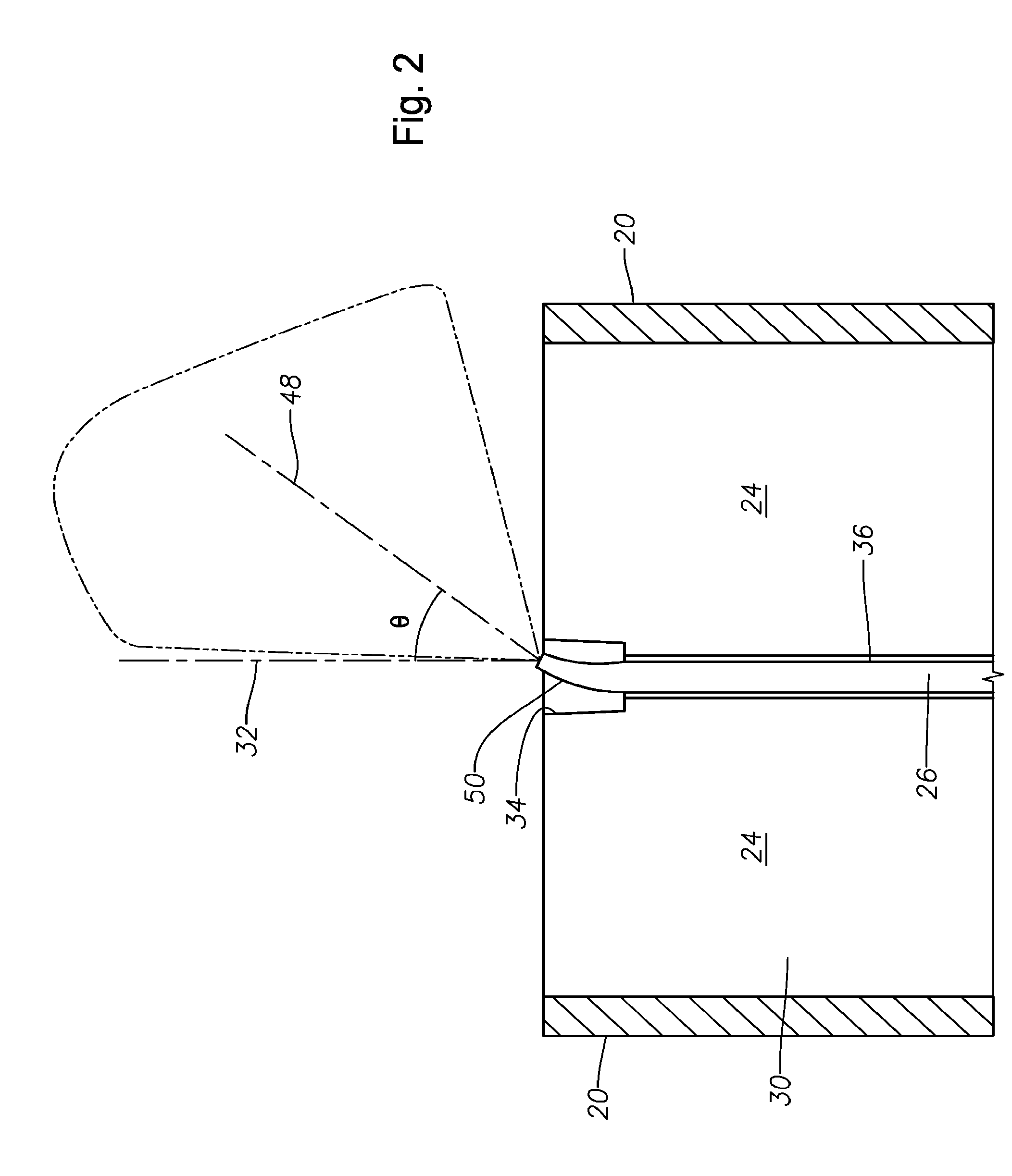
[0012]Certain embodiments may be directed to an endoillumination probe that has an optical fiber (such as a small diameter optical fiber) that emits light. The fiber may be configured to direct the illumination pattern of the emitted light in a particular manner. For example, the fiber may be bent or have an asymmetrically-shaped distal end to direct the light at an angle to the cylindrical axis of the probe. As another example, the distal end may be shaped to increase the divergence angle of the light beyond that which results from a distal end with a flat end normal to the fiber axis.

[0013]Referring now to the description and drawings, example embodiments of the disclosed apparatuses, systems, and methods are shown in detail. The description and drawings are not intended to be exhaustive or otherwise limit or restrict the claims to the specific embodiments shown in the drawings and disclosed in the description. Although the drawings represent possible embodiments, the drawings are...


PUM


Abstract

Certain embodiments of an endoilluminator may include a cannula, an intermediate material, and an optical fiber. The cannula has a substantially cylindrical shape that defines an interior region and has a cylindrical axis. The intermediate material is disposed within the interior region. The optical fiber is disposed within the intermediate material and has a fiber optical axis and a distal end configured to emit light. The emitted light has an illumination pattern with an illumination axis that is not parallel to the cylindrical axis.

Description

TECHNICAL FIELD[0001]The present disclosure relates generally to surgical instruments, and more particularly to ophthalmic endoilluminators with directed light.BACKGROUND[0002]Endoilluminators typically have a cannula filled with one or more optical fibers that emit light. Certain endoilluminators may direct light in a particular manner. For example, the optical fibers may be bent to direct light in a particular direction. As another example, the optical fibers may be shaped to direct light within a range of angles. These endoilluminators, however, may not be able to direct light in a suitable fashion in certain situations.BRIEF SUMMARY[0003]The description describes different embodiments of systems that may be used to direct light. For example, certain embodiments may include a cannula, an intermediate material, and an optical fiber. The cannula has a substantially cylindrical shape that defines an interior region and has a cylindrical axis. The intermediate material is disposed wi...

Claims


Application Information

Patent Timeline
Patent Type & Authority Applications(United States)
IPC IPC(8): A61B1/07A61B1/00
CPCA61B1/00183A61B1/07A61B90/30A61B3/0008A61B2090/306
Inventor AULD, JACK R.MARTIN, MICHAEL M.PAPAC, MICHAEL J.SMITH, RONALD T.YADLOWSKI, MICHAEL J.
Owner ALCON RES LTD
Why Eureka
Try Eureka