Methods for enhancing camera focusing performance using camera orientation

a technology of orientation and focusing, which is applied in the direction of camera focusing arrangement, printers, instruments, etc., can solve the problems of vcm solution typically running into af problems, af procedure can either take a longer time to find peak value, or not be able to find peak value at all, so as to enhance automatic camera focusing and enhance camera af performance. , the effect of saving power

Active Publication Date: 2014-12-18
NVIDIA CORP
View PDF2 Cites 18 Cited by
  • Summary
  • Abstract
  • Description
  • Claims
  • Application Information

AI Technical Summary

Benefits of technology

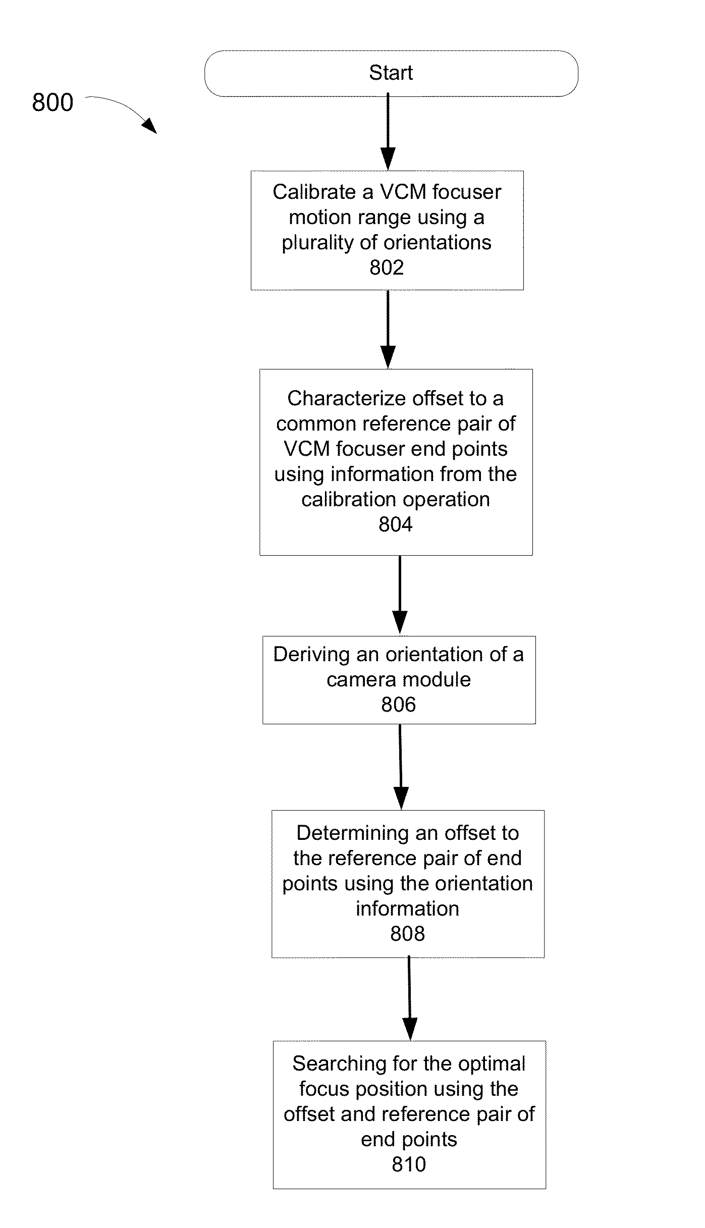
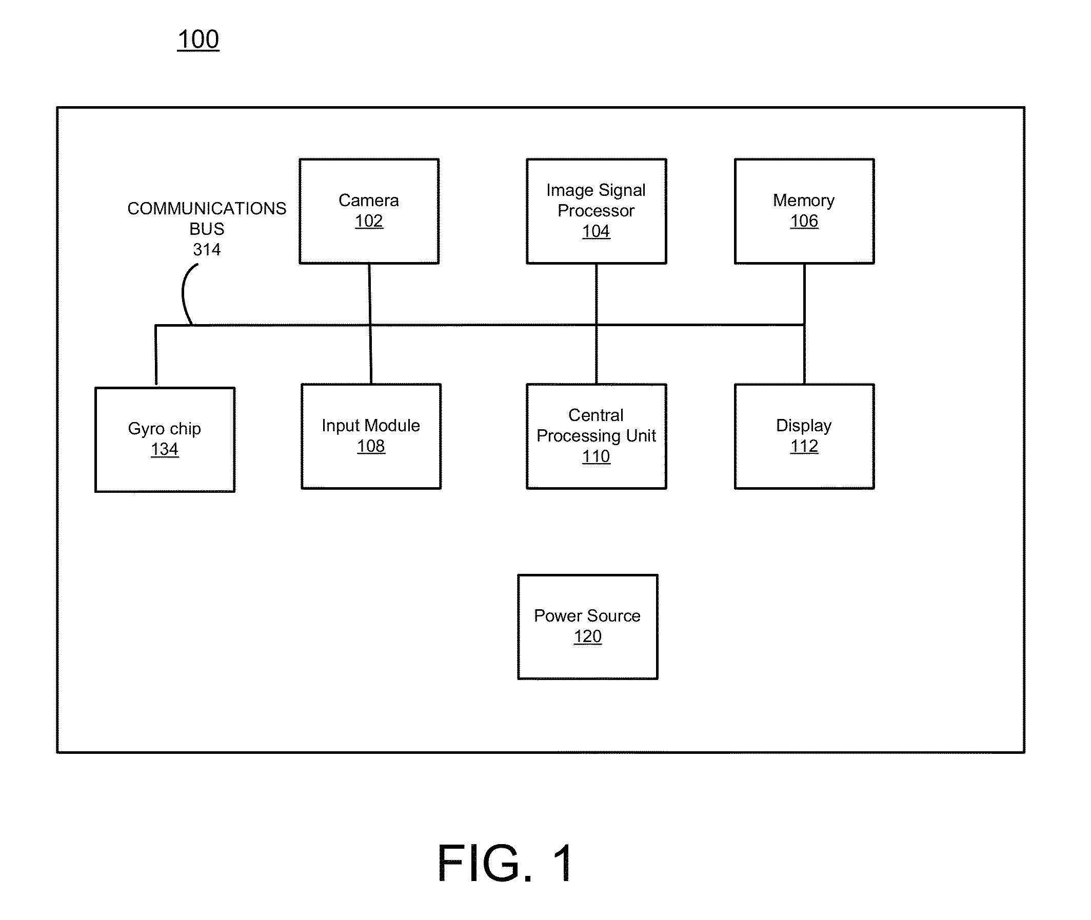
[0007]Accordingly, a need exists for systems and methods for enhancing the camera's AF performance by taking into account the orientation of a device employing a voice coil motor (VCM) focuser. The device orientation with respect to the gravitational field direction will influence the true range for the moveable component of the camera's lens assembly. In one embodiment, the present invention enhances automatic camera focusing on a portable electronic device by factoring in the orientation of the camera's optical axis relative to gravity during auto-focus. In another embodiment, the present invention temporarily suspends the AF procedure based on the speed of the device orientation change, so to conserve power during periods when the device and the image thereon are in a state of flux.

Problems solved by technology

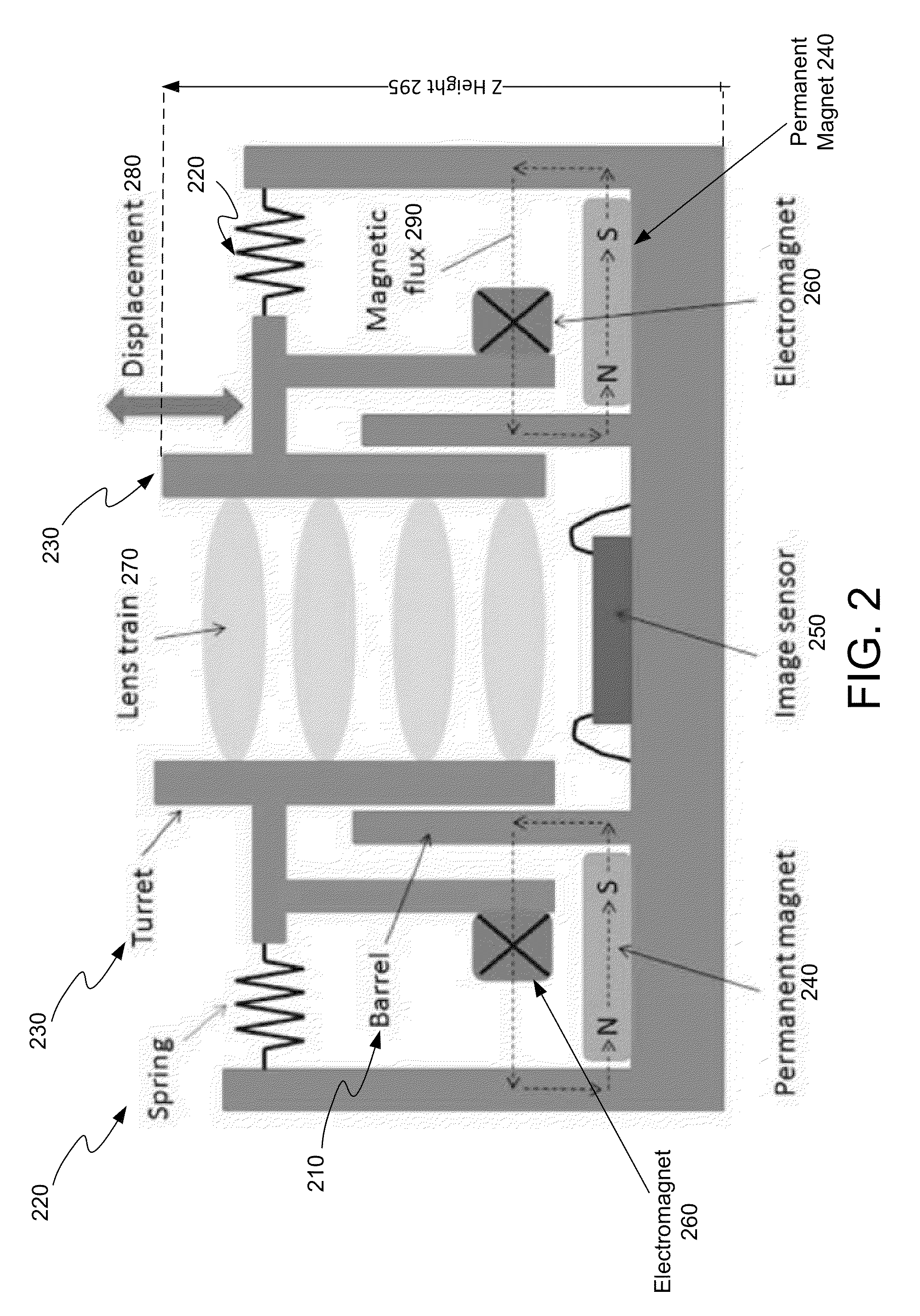
Conventional portable electronic device camera modules employing the VCM solution typically run into AF problems because the components of the VCM assembly are sensitive and, as a result, gravitational force applied to the moving component may restrict or alter its movement and can influence the range of allowable movement of the lens with respect to the image sensor depending on the orientation of the device.
Consequently, depending on the orientation of the device, the AF procedure can either take a longer time to find the peak value or, in the worst case, may not be able to find the peak value at all.

Method used


Image

  • Methods for enhancing camera focusing performance using camera orientation
  • Methods for enhancing camera focusing performance using camera orientation
  • Methods for enhancing camera focusing performance using camera orientation

Examples


Embodiment Construction

[0024]Reference will now be made in detail to the various embodiments of the present disclosure, examples of which are illustrated in the accompanying drawings. While described in conjunction with these embodiments, it will be understood that they are not intended to limit the disclosure to these embodiments. On the contrary, the disclosure is intended to cover alternatives, modifications and equivalents, which may be included within the spirit and scope of the disclosure as defined by the appended claims. Furthermore, in the following detailed description of the present disclosure, numerous specific details are set forth in order to provide a thorough understanding of the present disclosure. However, it will be understood that the present disclosure may be practiced without these specific details. In other instances, well-known methods, procedures, components, and circuits have not been described in detail so as not to unnecessarily obscure aspects of the present disclosure.

[0025]N...


PUM


Abstract

An electronic system for enhancing camera focusing on a portable electronic device is disclosed. The system comprises a body, a bus, and a camera module coupled to the bus and comprising a photosensitive substrate and a lens assembly wherein the lens assembly comprises a lens capable of being selectively moved to a distance from the photosensitive substrate for light focus thereon. Further, it comprises an accelerometer coupled to the bus and configured to generate orientation information, said orientation information indicating contemporaneous orientation of the body with respect to a predetermined reference. It also comprises a memory and a processor coupled to the bus. The memory comprises instructions that when executed implement an autofocus program configured to automatically determine the distance based on: 1) image data captured by said camera module; and 2) the orientation information generated by the accelerometer.

Description

FIELD OF THE INVENTION[0001]Embodiments according to the present invention generally relate to portable electronic devices and more specifically to methods for enhancing focusing on cameras for portable electronic devices.BACKGROUND OF THE INVENTION[0002]Facilitating automatic capture of high quality images with little or no user intervention is the primary objective in a camera system design for a consumer level portable electronic device, e.g., cell-phone, tablet, etc. Typically, consumers consider image sharpness to be a critical factor of final image quality. The sharpness of the final captured image is determined in significant part by the ability of the camera's auto-focus (AF) system to adjust the distance between the lens and image sensor in such a way as to render an object of interest at a certain distance from the camera onto the image sensor with an imperceptible amount of blur.[0003]Due to its ease of hardware integration, the passive AF approach has become the de facto...

Claims


Application Information

Patent Timeline
Patent Type & Authority Applications(United States)
IPC IPC(8): G03B13/36H04N5/232
CPCH04N5/232G03B13/36G03B3/10G03B17/18G03B2205/0069G03B2217/005H04N23/673H04N23/57H04N23/633
Inventor ZHANG, GUANGHUA GARYIP, KATHARINELIN, MICHAEL
Owner NVIDIA CORP
Why Eureka
Try Eureka