Hand tool joint

a hand tool and joint technology, applied in the field of mechanical joints, can solve the problems of unreliable hand tools, inability to easily disassemble hand tools, and generally more expensive production of hand tools with box joints than those with lap joints

Inactive Publication Date: 2014-12-25
COLTENE WHALEDENT INC
View PDF10 Cites 4 Cited by
  • Summary
  • Abstract
  • Description
  • Claims
  • Application Information

AI Technical Summary

Problems solved by technology

The rivet in a lap joint tends to loosen with time and use, eventually making the hand tool unreliable.
However, hand tools with box joints are generally more expensive to produce than those with lap joints.
Additionally, a deficiency commonly shared by hand tools having either a lap joint construction or a. box joint is that the hand tool cannot be easily disassembled.
This can be a detriment if the hand tool is intended for medical procedures where the hand tool needs to be sterilized.

Method used


Image

  • Hand tool joint
  • Hand tool joint
  • Hand tool joint

Examples


Embodiment Construction

[0016]The following detailed description is of the best mode or modes of the invention presently contemplated. Such description is not intended to be understood in a limiting sense, but to be an example of the invention presented solely for illustration thereof, and by reference to which in connection with the following description and the accompanying drawings one skilled in the art may be advised of the advantages and construction of the invention. In the various views of the drawings, like reference characters designate like or similar parts.

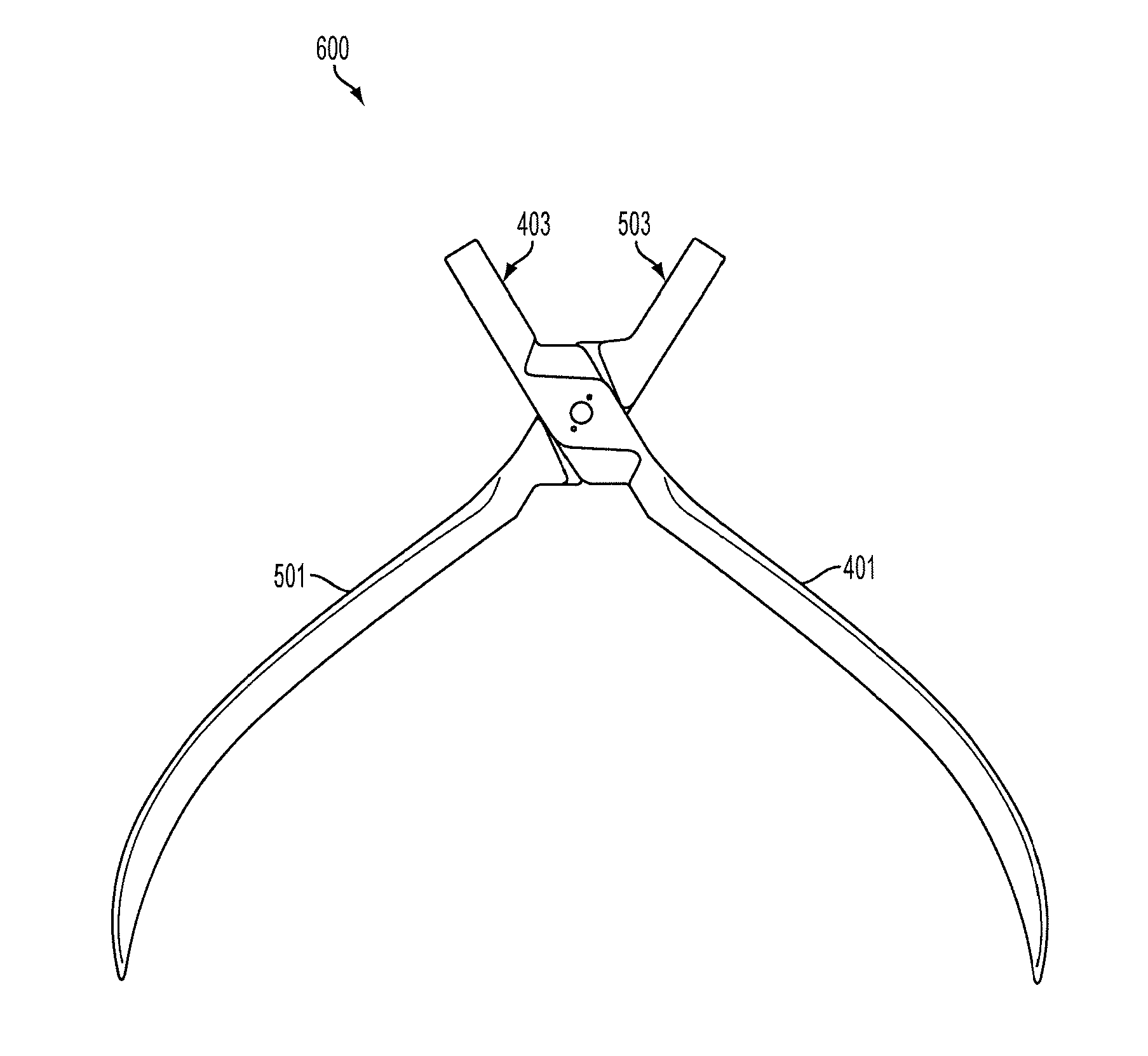
[0017]The components of the hand tool of the present invention will first be described in their unassembled configuration, With reference to FIGS. 4A and 4B, depicted is a first hand tool component (401) having a jaw portion (403), joint portion (405), and a handle portion (407). The joint portion (405) comprises a hole (409), a bearing surface (411), a first slot (413), and a second slat (415).

[0018]FIGS. 5A and 5B depict a second hand tool ...


PUM


Abstract

Disclosed herein is a hand tool comprising a first hand tool member comprising a pin, a hole, a bearing surface, and at least one groove, and a second hand tool member comprising a hole, a bearing surface, and at least one groove. The groove of the first hand tool member engages the groove of the second hand tool member when the hand tool is in a closed position. Further, the groove of the first hand tool member disengages from the groove of the second hand tool member when the hand tool is in a fully open position.

Description

CROSS REFERENCE TO RELATED APPLICATIONS[0001]The present application claims priority to U.S. Provisional Application No. 61 / 585,014, filed Jan. 10, 2012, the entire content of which is incorporated by reference in its entiretyFIELD OF THE INVENTION[0002]The invention is directed to a mechanical joint for hand tools such as pliers or the like.BACKGROUND OF THE INVENTION[0003]Hand tools typically employ two types of pivot joints: lap joints and box joints. In both types of joints, no more than fifty percent of the cross--sectional area of at least one of the jaws is available to resist the strain put upon the hand tool when in use, Depicted in FIG. 1 is a hand tool (100) having a lap joint, wherein each half of the hand tool (101, 102) is joined by at an overlapping region having a. recess (103, 104). For example, each half of the hand tool (101, 102) may be machined to define a recess (103, 104) that is half the width of the hand tool. This produces a hand tool 100 having a combined ...

Claims


Application Information

Patent Timeline
Patent Type & Authority Applications(United States)
IPC IPC(8): B25B7/08B25B7/02
CPCB25B7/02B25B7/08A61B17/2816A61C3/10A61C3/14A61C7/04B25B7/06
Inventor SILDVE, PETERMUSTARD, TERRY
Owner COLTENE WHALEDENT INC
Why Eureka
Try Eureka