Thermal barrier coating systems and processes therefor

a technology of thermal barrier coating and coating system, which is applied in the direction of superimposed coating process, coating, transportation and packaging, etc., can solve the problems of reducing the thermal conductivity of the thermal barrier coating system. , to achieve the effect of reducing the porousness and significantly enhancing the thermal resistance of the coating system

Inactive Publication Date: 2014-12-25
GENERAL ELECTRIC CO
View PDF8 Cites 6 Cited by
  • Summary
  • Abstract
  • Description
  • Claims
  • Application Information

AI Technical Summary

Benefits of technology

[0013]A technical effect of the invention is the ability of the coating system to withstand thermal cycling when subjected to CMAS contaminants. The high yttria content of the outer ceramic layer enables the outer ceramic layer to react with CMAS to form a protective layer that inhibits further infiltration of molten CMAS into the coating system. Significantly, the relative thicknesses and densities of the inner and outer ceramic layers have been shown to be critical to the spallation resistance of the coating system. In particular, the spallation resistance of the coating system has been shown to be significantly enhanced by limiting the thickness of the outer ceramic layer relative to the thickness of the inner ceramic layer and by ensuring that the outer ceramic layer is denser (less porous) than the inner ceramic layer.
[0014]Other aspects and advantages of this invention will be better appreciated from the following detailed description.

Problems solved by technology

Zirconia is stabilized to inhibit a tetragonal to monoclinic crystal phase transformation at about 1000° C., which results in a volume change that can cause spallation.
TBCs formed by the various methods noted above generally have a lower thermal conductivity than a dense ceramic of the same composition as a result of the presence of microstructural defects and pores at and between grain boundaries of the TBC microstructure.
Under service conditions, hot section engine components protected by a TBC system can be susceptible to various modes of damage, including erosion, oxidation and corrosion from exposure to the gaseous products of combustion, foreign object damage (FOD), and attack from environmental contaminants.
These environmental contaminants are in addition to the corrosive and oxidative contaminants that result from the combustion of fuel.
However, all of these contaminants can adhere to the surfaces of the hot section components, including those that are protected with a TBC system.
Some contaminants may result in TBC loss over the life of the components.
The molten CMAS resolidifies within cooler subsurface regions of the TBC, where it interferes with the compliance of the TBC and can lead to spallation and degradation of the TBC, particularly during thermal cycling as a result of interfering with the ability of the TBC to expand and contract.
In addition to loss of compliance, deleterious chemical reactions with yttria and zirconia within the TBC, as well as with the thermally-grown oxide at the bond coating / TBC interface, can occur and cause degradation of the TBC system.
Once the passive thermal barrier protection provided by the TBC has been lost, continued operation of the engine will lead to oxidation of the base metal beneath the TBC system, which may ultimate lead to failure of the component by burn through cracking
However, grinding during manufacture and assembly, as well as grinding and rubbing with turbine shrouds during gas turbine engine operation, result in the use and reliance on the alumina layer difficult and impractical.
In addition, the alumina layer adds manufacturing cost and complexity, especially for turbine blades that are subjected to gas and particle erosion and may have different requirements for the alumina coating in order to minimize erosion.
In addition, thicker alumina layers are subject to coefficient of thermal expansion mismatches within the TBC coating system, resulting in thermal strains during cycling.

Method used


Image

  • Thermal barrier coating systems and processes therefor
  • Thermal barrier coating systems and processes therefor
  • Thermal barrier coating systems and processes therefor

Examples


Embodiment Construction

[0019]The present invention is generally applicable to components subjected to high temperatures, and particularly to components such as the high and low pressure turbine vanes (nozzles) and blades (buckets), shrouds, combustor liners and augmentor hardware of gas turbine engines. The invention provides TBC systems that are suitable for protecting the surfaces of gas turbine engine components that are subjected to hot combustion gases. While the advantages of this invention will be described with reference to gas turbine engine components, the teachings of the invention are generally applicable to any component on which a TBC may be used to protect the component from a high temperature environment.

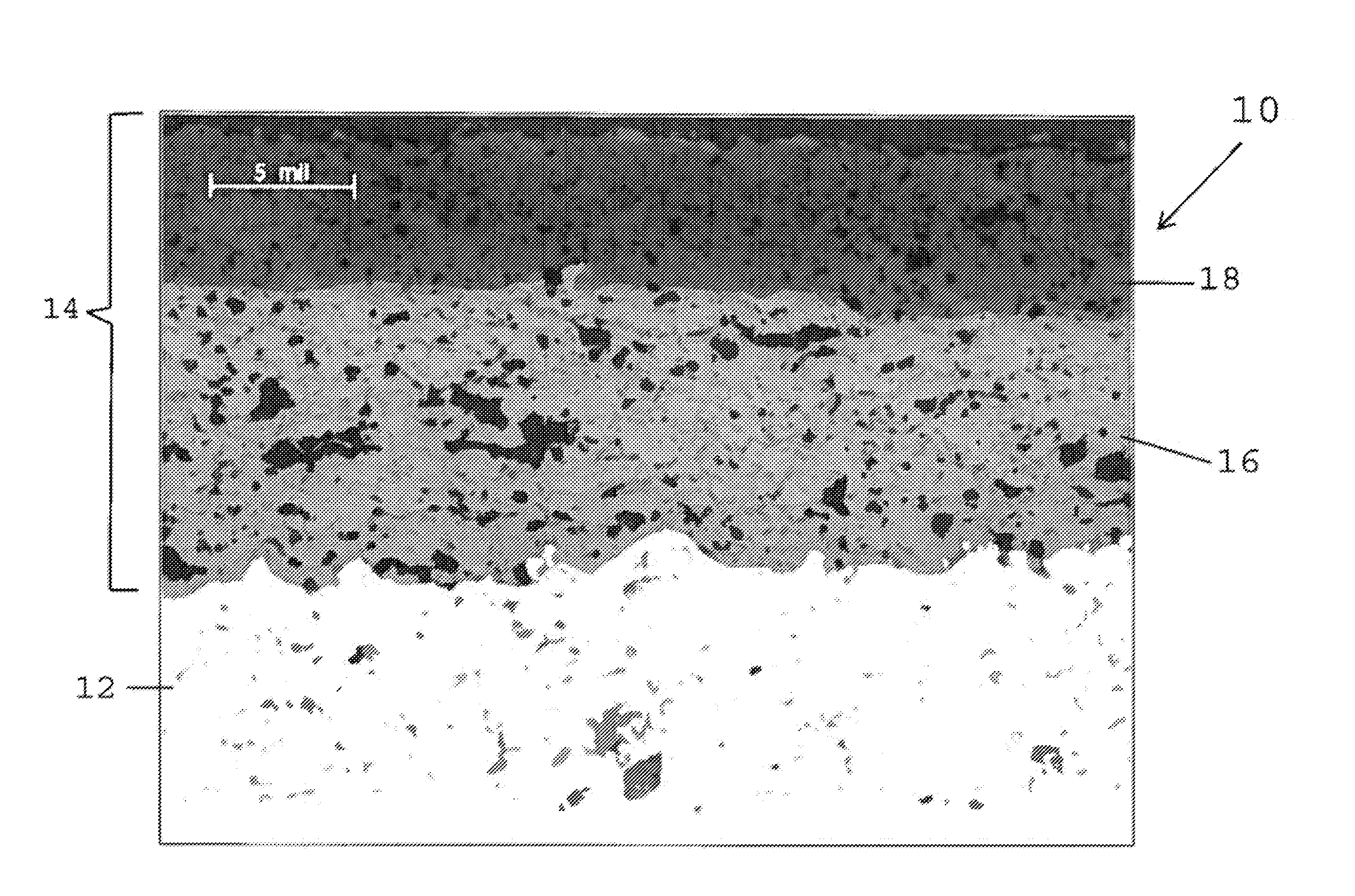
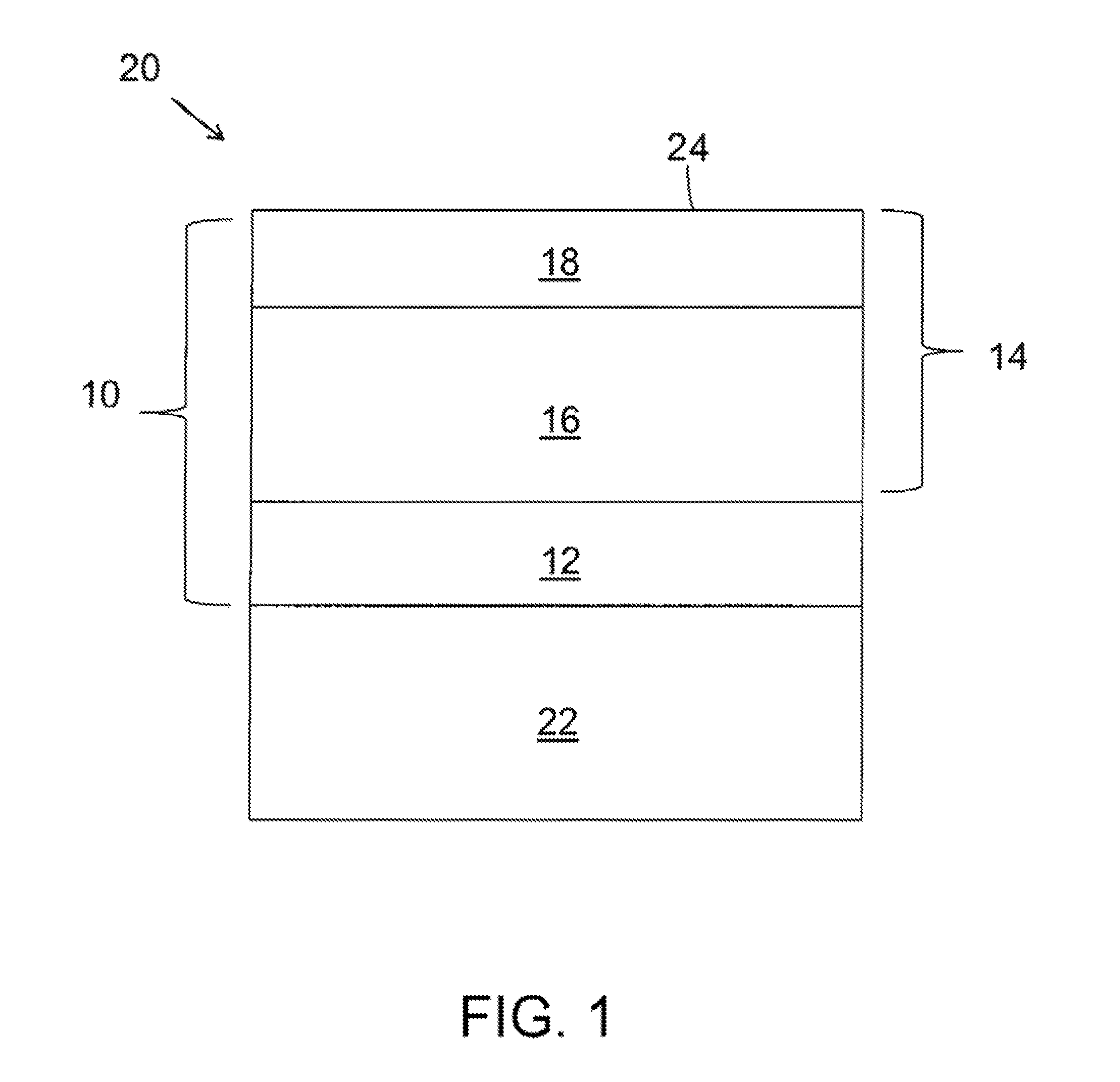
[0020]An embodiment of a TBC system 10 of this invention is schematically represented in FIG. 1 as being applied to the surface of a substrate 22, which in combination with the TBC system 10 yields a coated component 20. The TBC system 10 is shown as including a bond coat 12 that overlies ...


PUM

PropertyMeasurementUnit
temperatureaaaaaaaaaa
thicknessaaaaaaaaaa
thicknessaaaaaaaaaa

Abstract

Coating systems and processes by which the coating systems can be deposited to be resistant to contaminants, and particularly resistant to infiltration and damage caused by CMAS. The coating systems include inner and outer ceramic layers, each having a microstructure characterized by splats and horizontal porosity. The inner ceramic layer consists essentially of zirconia stabilized by about 6 to about 9 weight percent yttria. The outer ceramic layer overlies and contacts the inner ceramic layer to define the outermost surface of the coating system. The outer ceramic layer consists essentially of zirconia stabilized by about 25 to about 75 weight percent yttria, has a thickness that is less than the thickness of the inner ceramic layer, and has a porosity level that is lower than that of the inner ceramic layer.

Description

CROSS REFERENCE TO RELATED APPLICATIONS[0001]This is a division patent application of co-pending U.S. patent application Ser. No. 13 / 341,247, filed Dec. 30, 2011, which claimed the benefit of U.S. Provisional Application No. 61 / 546,793, filed Oct. 13, 2011. The contents of these prior applications are incorporated herein by reference.BACKGROUND OF THE INVENTION[0002]This invention relates to coatings capable of use on components exposed to high temperatures, such as the hostile thermal environment of a gas turbine engine. More particularly, this invention is directed to a thermal barrier coating (TBC) capable of exhibiting resistance to thermal cycling and infiltration by contaminants, for example, of types that may be present in the operating environment of a gas turbine engine.[0003]The use of thermal barrier coatings (TBCs) on components such as combustors, high pressure turbine (HPT) blades, vanes and shrouds is increasing in commercial as well as military gas turbine engines. T...

Claims


Application Information

Patent Timeline
Patent Type & Authority Applications(United States)
IPC IPC(8): C23C4/10C23C4/18
CPCC23C4/18C23C4/105C04B35/486C04B35/505C04B2235/3225C04B2235/3244C04B2235/76C23C4/02C23C28/3215C23C28/3455C23C4/11Y10T428/12549Y10T428/12618Y10T428/2495Y02T50/60
Inventor NAGARAJ, BANGALORE ASWATHATOMLINSON, THOMAS JOHN
Owner GENERAL ELECTRIC CO
Why Eureka
Try Eureka