Device for monitoring surroundings of machinery

a technology for monitoring equipment and surroundings, applied in the direction of soil shifting machines/dredgers, television systems, transportation and packaging, etc., can solve the problems of difficult backward direction and inability to confirm by sight (visual recognition)

Inactive Publication Date: 2015-01-08
NIHON KENKI CO LTD
View PDF16 Cites 33 Cited by
  • Summary
  • Abstract
  • Description
  • Claims
  • Application Information

AI Technical Summary

Benefits of technology

The present invention allows for the creation of a bird's eye view image of the surroundings, including machinery, by combining images captured by cameras and adjusting the display areas based on the camera heights. This ensures that an appropriate bird's eye view image is always prepared and displayed, regardless of changes in the vehicle body height.

Problems solved by technology

The technical problem addressed in this patent text relates to improving visibility when operating an excavator or power shovel through the installation of cameras on the front left side of the upper swinging parts. However, current solutions require multiple cameras placed throughout the vehicle body or frame to provide a comprehensive view of the surroundings.

Method used


Image

  • Device for monitoring surroundings of machinery
  • Device for monitoring surroundings of machinery
  • Device for monitoring surroundings of machinery

Examples


Embodiment Construction

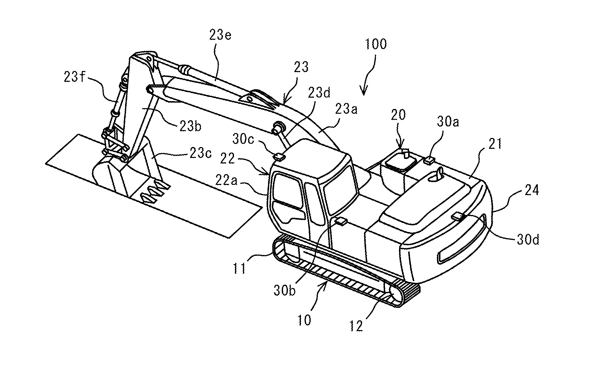
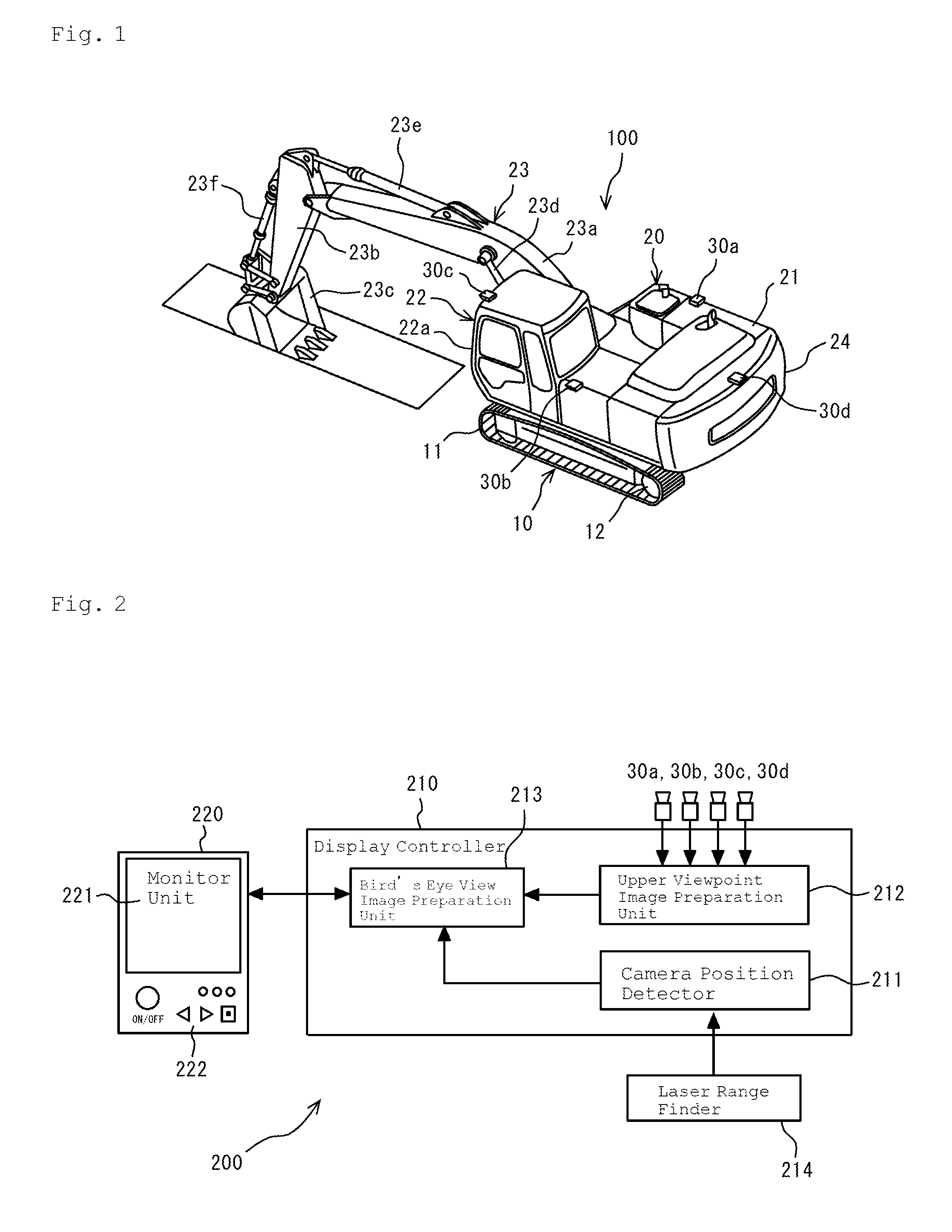
[0030]Now, embodiments of the present invention will be described with reference to the accompanying drawings. FIG. 1 is a general perspective view of an excavator or power shovel 100, which is one kind of machinery according to one embodiment of the present invention. As illustrated, the power shovel 100 has, as its main components, a lower traveling body 10 and an upper swinging body 20 swingably (pivotably) provided on the lower traveling body 10. The lower traveling body 10 has a pair of crawlers 11 (11) that are provided in parallel to each other on a frame (not shown) of the traveling body. Each of these crawlers 11 (11) is equipped with a hydraulically-operated traveling motor 12 for driving an associated crawler belt (track) for traveling.

[0031]The upper swinging body 20 has, its main components, an engine room 21 for housing an engine, which is located on the swinging body frame (not shown), as well as various equipment such as a battery and a fuel tank, a driver's cab 22 p...


PUM


Abstract

A surroundings monitoring device (200) provided on machinery which changes its vehicle body height. The surroundings monitoring device includes a plurality of cameras (30) that image the surroundings thereof, a unit for converting the original images (31) taken by the cameras (30) to overhead viewpoint images (35), a unit for combining the overhead viewpoint images (35) to generate a bird's-eye image (300), a unit for displaying the bird's-eye image (300), and a unit for detecting the positions of the cameras. The bird's-eye image-generating unit adjusts the display region (e) for each overhead viewpoint image (35) on the basis of the detected height of the camera concerned, and combines the overhead viewpoint images. It is therefore possible to always generate and display an accurate bird's-eye image (300) even when the vehicle body height changes significantly.

Description


Claims


Application Information

Patent Timeline
Owner NIHON KENKI CO LTD
Why Eureka
Try Eureka