Supercharge Your Innovation With Domain-Expert AI Agents!

High pressure container

a container and high pressure technology, applied in the field of high pressure containers, can solve the problems of not being able to suitably control the timing of making or manufacturing the required products, affecting the quality of the product, so as to improve the structure or configuration, resist a higher pressure, and the temperature is higher.

Inactive Publication Date: 2015-01-08
SHUEN HWA ENTERPRISE
View PDF3 Cites 0 Cited by
  • Summary
  • Abstract
  • Description
  • Claims
  • Application Information

AI Technical Summary

Benefits of technology

The present invention provides a high temperature and high pressure container with an improved structure or configuration for heating and resisting the higher pressure. The container includes a housing, a casing, and a pressurizing device. The pressurizing device is connected to the casing for supplying the heated and / or pressurized air into the container for heating and / or pressurizing the work piece. The housing has an insert for heat insulation. The container has an open end portion and a cover for positioning and retaining the work piece. The casing can be easily heated, pressurized, and cooled for resisting the higher pressure. The technical effects of this invention are fast heating and cooling of the work piece, strong structure or configuration to resist the higher pressure, and efficient production.

Problems solved by technology

However, the typical furnaces are normally required to be formed or provided with a great thickness for resisting the higher pressure and the higher temperature, but it will take a long time to heat the typical furnaces or the typical high pressure containers to the required temperature, and it will also take a long time to have the typical furnaces or the typical high pressure containers cooled to the required temperature.
However, the typical furnaces or high pressure containers may take a long time to heat the solidified materials or thermoplastic materials to the required temperature, and it will also take a long time to have the solidified materials or thermoplastic materials cooled to the required temperature, such that the timing for making or manufacturing the required products may not be suitably controlled.

Method used


Image

  • High pressure container
  • High pressure container

Examples


Embodiment Construction

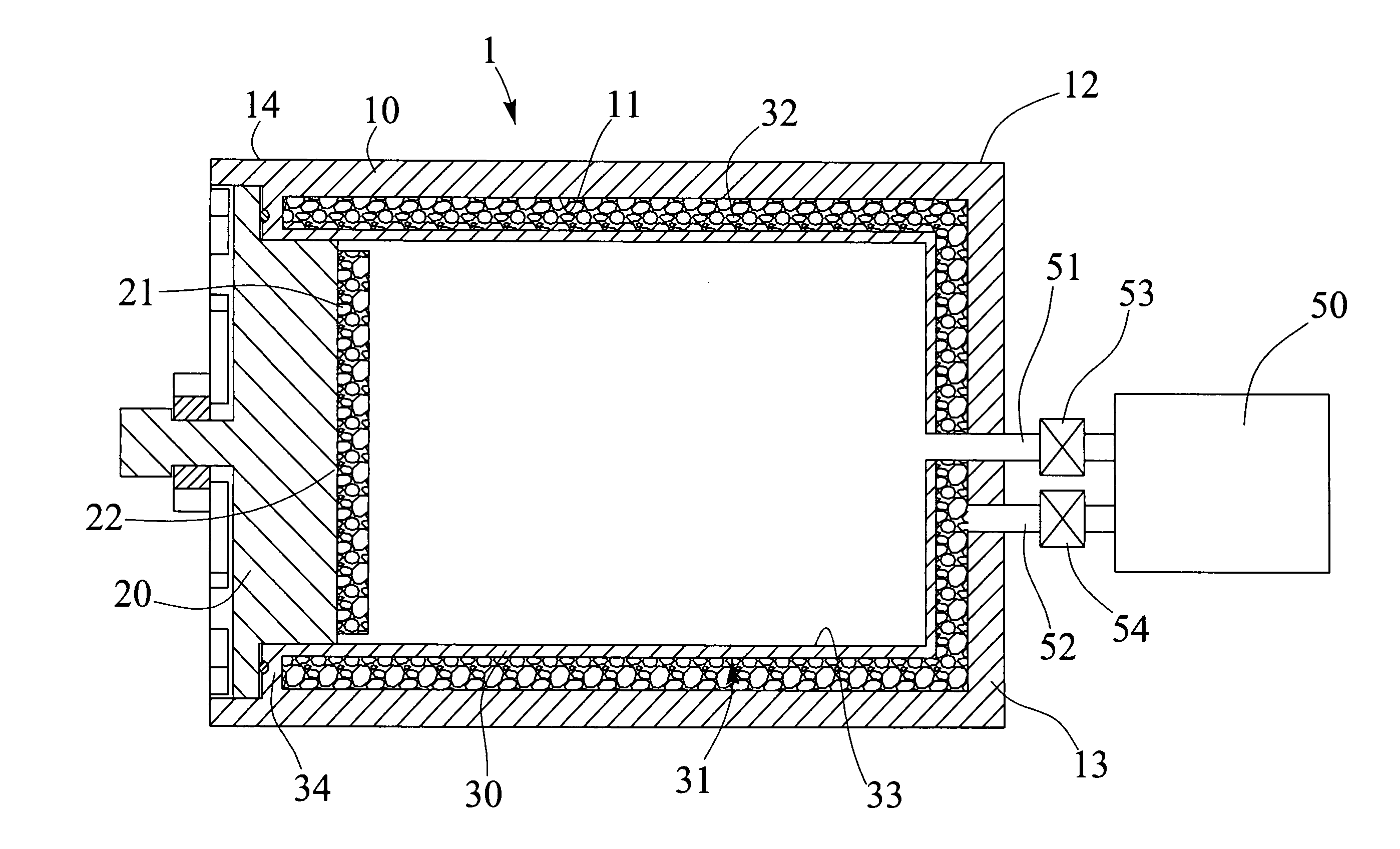
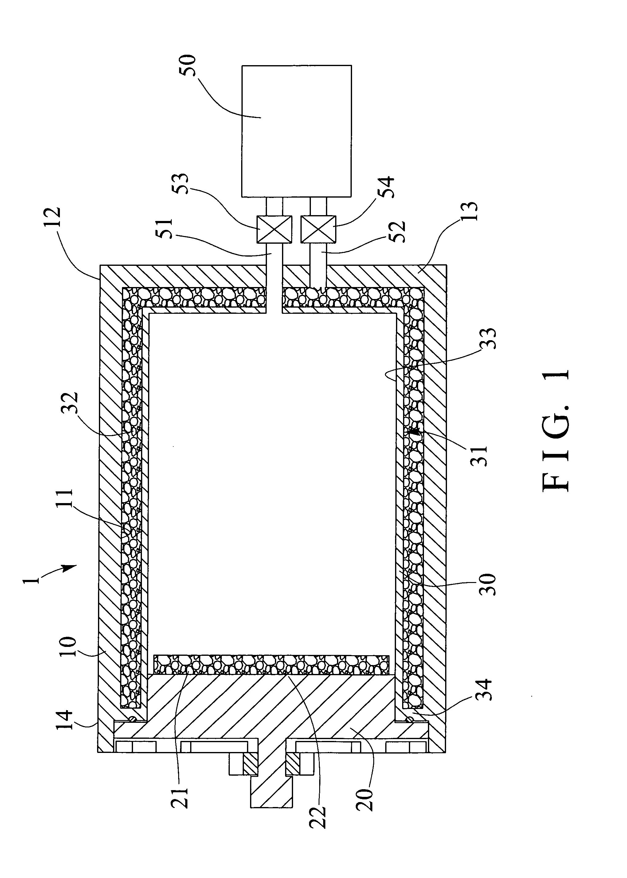
[0017]Referring to the drawing FIG. 1, a furnace facility or high pressure container 1 in accordance with the present invention comprises an outer receptacle or container or housing 10 including a compartment or space or chamber 11 formed therein, and including one or first end portion 12 having an end panel or end wall 13 formed or provided therein, and including an open or other or second end portion 14 for receiving or engaging with a cover 20 which may be solidly and stably attached or mounted or secured to the housing 10 with latches or locks or catches or fastening materials or members or elements (not illustrated) or the like for suitably blocking or enclosing the open or second end portion 14 of the housing 10.

[0018]The housing 10 further includes an inner receptacle or casing 30 disposed or attached or mounted or supported or engaged in the chamber 11 of the housing 10, and preferable, but not necessary that the casing 30 is arranged parallel to the housing 10, the casing 3...


PUM


Abstract

A high pressure container includes a casing disposed in a housing and spaced from the housing for forming a peripheral space between the housing and the casing, the casing includes a compartment and spaced from the peripheral space that is formed between the housing and the casing, and a pressurizing device is connected to the compartment of the casing with a pipe for supplying a heated or pressurized air into the casing in order to heat or pressurize the work piece to the required higher pressure or temperature, and the pressurizing device is coupled to the peripheral space that is formed between the housing and the casing with a tube for supplying a pressurized air into the peripheral space for balancing the pressure.

Description

BACKGROUND OF THE INVENTION[0001]1. Field of the Invention[0002]The present invention relates to a high pressure container, and more particularly to a high temperature and high pressure container including an improved structure or configuration for heating the work piece to a higher temperature and resisting a higher pressure and for allowing the high temperature container to be quickly lowered to a lower temperature.[0003]2. Description of the Prior Art[0004]Typical steel materials are required to be subjected with various heating processes or procedures with various kinds of furnace facilities, and the furnace facilities normally will be heated to a higher temperature and a higher pressure in order to make or manufacture the required products.[0005]For example, U.S. Pat. No. 4,227,874 to Nugent, U.S. Pat. No. 4,582,301 to Wunning, U.S. Pat. No. 4,767,320 to Sasaki et al., U.S. Pat. No. 5,848,890 to McCormick, and U.S. Pat. No. 7,520,746 to Johnston et al. disclose several of the t...

Claims


Application Information

Patent Timeline
Patent Type & Authority Applications(United States)
IPC IPC(8): F27D7/06
CPCF27D2007/063F27D7/06
Inventor CHAN, KUO LIANG
Owner SHUEN HWA ENTERPRISE
Features
  • R&D
  • Intellectual Property
  • Life Sciences
  • Materials
  • Tech Scout
  • Unparalleled Data Quality
  • Higher Quality Content
  • 60% Fewer Hallucinations
Learn More