Method and apparatus for detecting intrusion into vehicle

a technology for intrusion detection and vehicles, applied in anti-theft devices, distance measurement, instruments, etc., can solve problems such as sensor failure to detect intrusion, sensor malfunction, and vehicle theft, and achieve the effect of preventing vehicle theft and th

Inactive Publication Date: 2015-01-15
ELECTRONICS & TELECOMM RES INST
View PDF10 Cites 3 Cited by
  • Summary
  • Abstract
  • Description
  • Claims
  • Application Information

AI Technical Summary

Benefits of technology

[0016]In accordance with another aspect of the present invention, there is provided an apparatus for detecting intrusion into a vehicle, including a first sensor unit disposed in the left side-view mirror of a vehicle, and configured to include an acceleration sensor and a laser sensor; a second sensor unit disposed in a right side-view mirror of the vehicle, and configured to include an acceleration sensor and a laser sensor; and a control unit configured to detect the sudden movement of the vehicle based on the results of the comparison between the measured and initial values of the acceleration sensor included in each of the first and second sensor units, and to detect intrusion into the vehicle using the laser sensor of the first or second sensor unit.
[0017]The control unit may be configured to set a distance between each of the side-view mirrors and a reference point of the vehicle as a reference distance before detecting the intrusion into the vehicle; to measure a current distance between each of the side-view mirror and the reference point using the laser sensor when the sudden movement of the vehicle is detected; and to detect intrusion into the vehicle by comparing the measured current distance with the reference distance.
[0018]The control unit may be configured to, before detecting intrusion into the vehicle, set the laser sensor to a standby state if the sudden movement of the vehicle is not detected.
[0019]The first sensor unit may be configured to determine data validity by comparing a first measured value sensed by a first acceleration sensor of the first sensor unit with a threshold corresponding to the first acceleration sensor, and to determine that the first measured value is valid if the first measured value is higher than the threshold corresponding to the first acceleration sensor.
[0020]The second sensor unit may be configured to determine data validity by comparing a second measured value sensed by a second acceleration sensor of the second sensor unit with a threshold corresponding to the second acceleration sensor, and to determine that the second measured value is valid if the second measured value is higher than the threshold corresponding to the second acceleration sensor.
[0021]The control unit may be configured to determine that a door including a side-view mirror in which a sensor unit having a higher measured value is disposed has been moved if there is a difference between a first measured value sensed by a first acceleration sensor of the first sensor unit and a second measured value sensed by a second acceleration sensor of the second sensor unit.

Problems solved by technology

As vehicles increase and continue to have higher quality, the stealing of vehicles and the theft of articles within vehicles are increasing.
Such sensors are problematic in that the sensors do not detect intrusion due to their sensitivity, for example, upon a door being opened very slowly because the sensors are used to detect relatively large movement.
Furthermore, the erroneous operation of these sensors malfunctions may occur due to sudden movement attributable to a storm and heavy rain in connection with the setting of the sensitivity and threshold of the sensors because the sensors are acceleration sensors for measuring the sudden movement of a vehicle.
However, these methods are problematic in that high battery consumption attributable to continuous operation occurs, it is difficult to select the location of installation in order to avoid erroneous operation attributable to high sensitivity, and wiring is complicated.

Method used


Image

  • Method and apparatus for detecting intrusion into vehicle
  • Method and apparatus for detecting intrusion into vehicle
  • Method and apparatus for detecting intrusion into vehicle

Examples


Embodiment Construction

[0028]The present invention is described in detail below with reference to the accompanying drawings. Repeated descriptions and descriptions of known functions and configurations which have been deemed to make the gist of the present invention unnecessarily obscure will be omitted below. The embodiments of the present invention are intended to fully describe the present invention to a person having ordinary knowledge in the art to which the present invention pertains. Accordingly, the shapes, sizes, etc. of components in the drawings may be exaggerated to make the description clear.

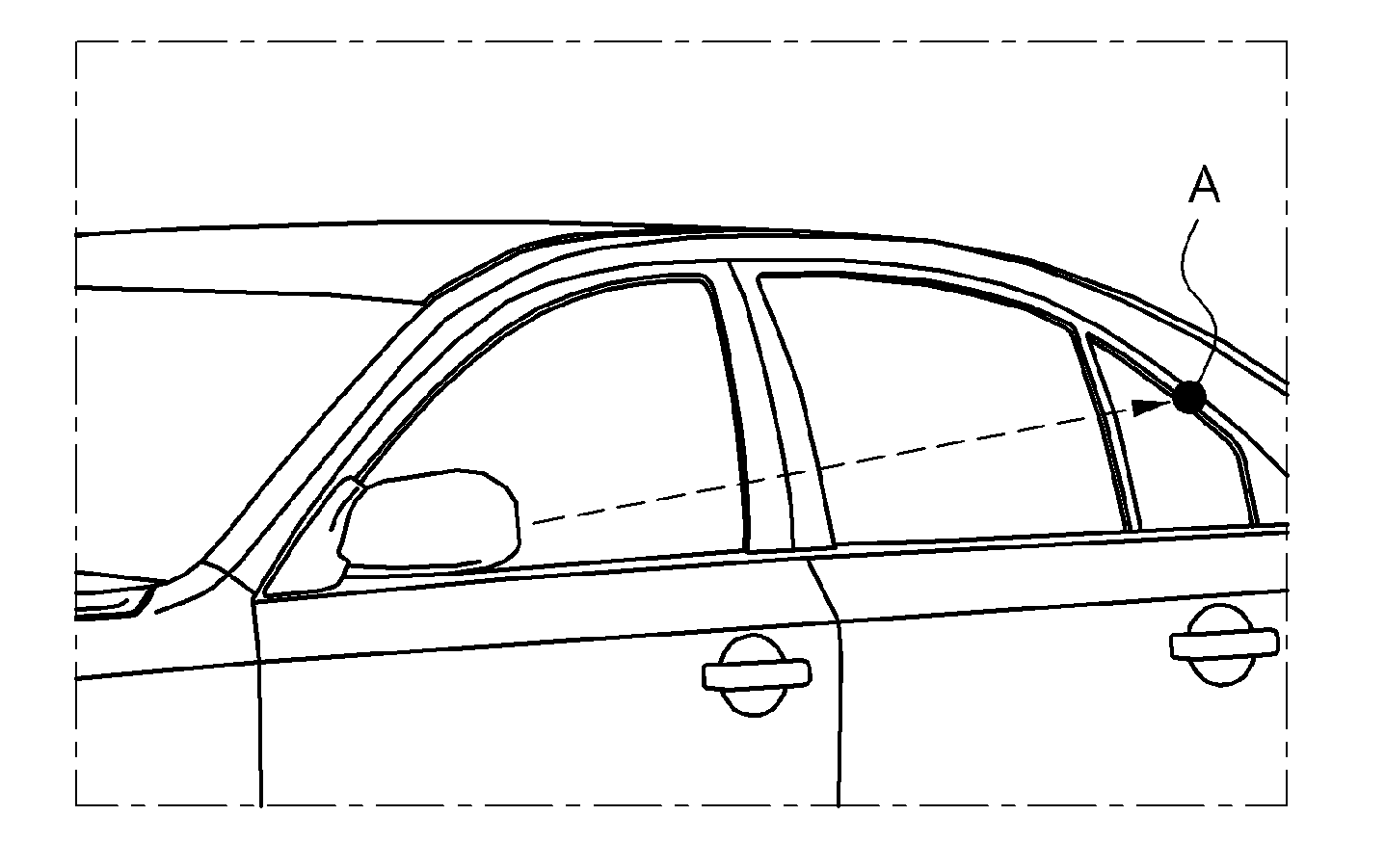
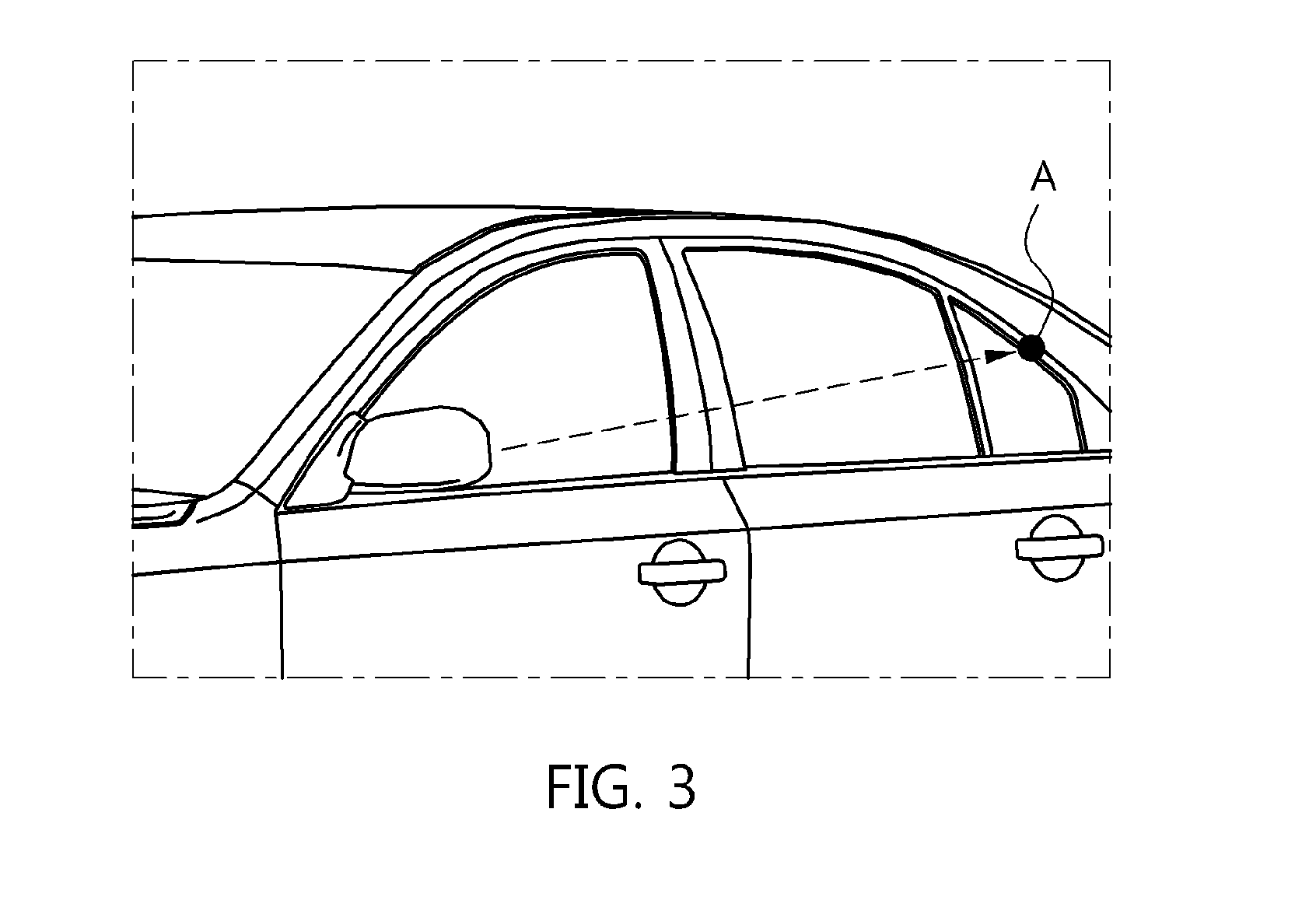
[0029]A method and apparatus for detecting intrusion through an open door or a window of a door using wireless sensor nodes within side-view mirrors according to embodiments of the present invention are described in detail below with reference to the accompanying drawings.

[0030]That is, the present invention is directed to a method capable of solving the problems of a conventional system for detecting int...


PUM


Abstract

An apparatus and method for detecting intrusion into a vehicle are disclosed. The apparatus includes a first sensor unit, a second sensor unit, and a control unit. The first sensor unit is disposed in the left side-view mirror of a vehicle, and includes an acceleration sensor and a laser sensor. The second sensor unit is disposed in the right side-view mirror of the vehicle, and includes an acceleration sensor and a laser sensor. The control unit detects the sudden movement of the vehicle based on the results of the comparison between the measured and initial values of the acceleration sensor included in each of the first and second sensor units, and detects intrusion into the vehicle using the laser sensor of the first or second sensor unit.

Description

CROSS REFERENCE TO RELATED APPLICATION[0001]This application claims the benefit of Korean Patent Application No. 10-2013-0082981, filed on Jul. 15, 2013, which is hereby incorporated by reference in its entirety into this application.BACKGROUND OF THE INVENTION[0002]1. Technical Field[0003]The present invention relates generally to a method and apparatus for detecting intrusion into a vehicle and, more particularly, to a method and apparatus for detecting intrusion into a vehicle through an open door of a vehicle or a window of a door using wireless sensor nodes disposed within side-view mirrors.[0004]2. Description of the Related Art[0005]As vehicles increase and continue to have higher quality, the stealing of vehicles and the theft of articles within vehicles are increasing. The investigation of Japan's National Policy Agency reveals that the total number of crimes aiming at the stealing of vehicles and the theft of parts and articles within vehicles was 175,065 cases in 2012 and...

Claims


Application Information

Patent Timeline
Patent Type & Authority Applications(United States)
IPC IPC(8): B60R25/32G01P15/00G01C3/02
CPCB60R25/32G01P15/00G01C3/02B60R25/1001B60R25/1004
Inventor LEE, SEUNGJUNKIM, DOHYUNKIM, KYONGHOHAM, HOSANG
Owner ELECTRONICS & TELECOMM RES INST
Why Eureka
Try Eureka