Wireless confinement and training system for an animal

Inactive Publication Date: 2007-08-16
WESTRICK MICHAEL
View PDF18 Cites 9 Cited by
  • Summary
  • Abstract
  • Description
  • Claims
  • Application Information

AI Technical Summary

Benefits of technology

[0010] An advantage of the present invention is that since a wire loop antenna is not needed, a system can be more easily set up and relocated if the need arises.
[0011] Another advantage of the present invention is that the bou

Problems solved by technology

A problem with this type of system is that it is difficult and time consuming to install and maintain the underground loop antenna.
Additionally, once the wire loop antenna is laid into the ground, the boundaries of the animal's confinement area are fixed and cannot be easily modified.
Often the cost of installation is several times the a

Method used


Image

  • Wireless confinement and training system for an animal
  • Wireless confinement and training system for an animal
  • Wireless confinement and training system for an animal

Examples


Example

[0021] Corresponding reference characters indicate corresponding parts throughout the several views. The exemplification set out herein illustrates one embodiment of the invention, in one form, and such exemplification is not to be construed as limiting the scope of the invention in any manner.

DETAILED DESCRIPTION OF THE INVENTION

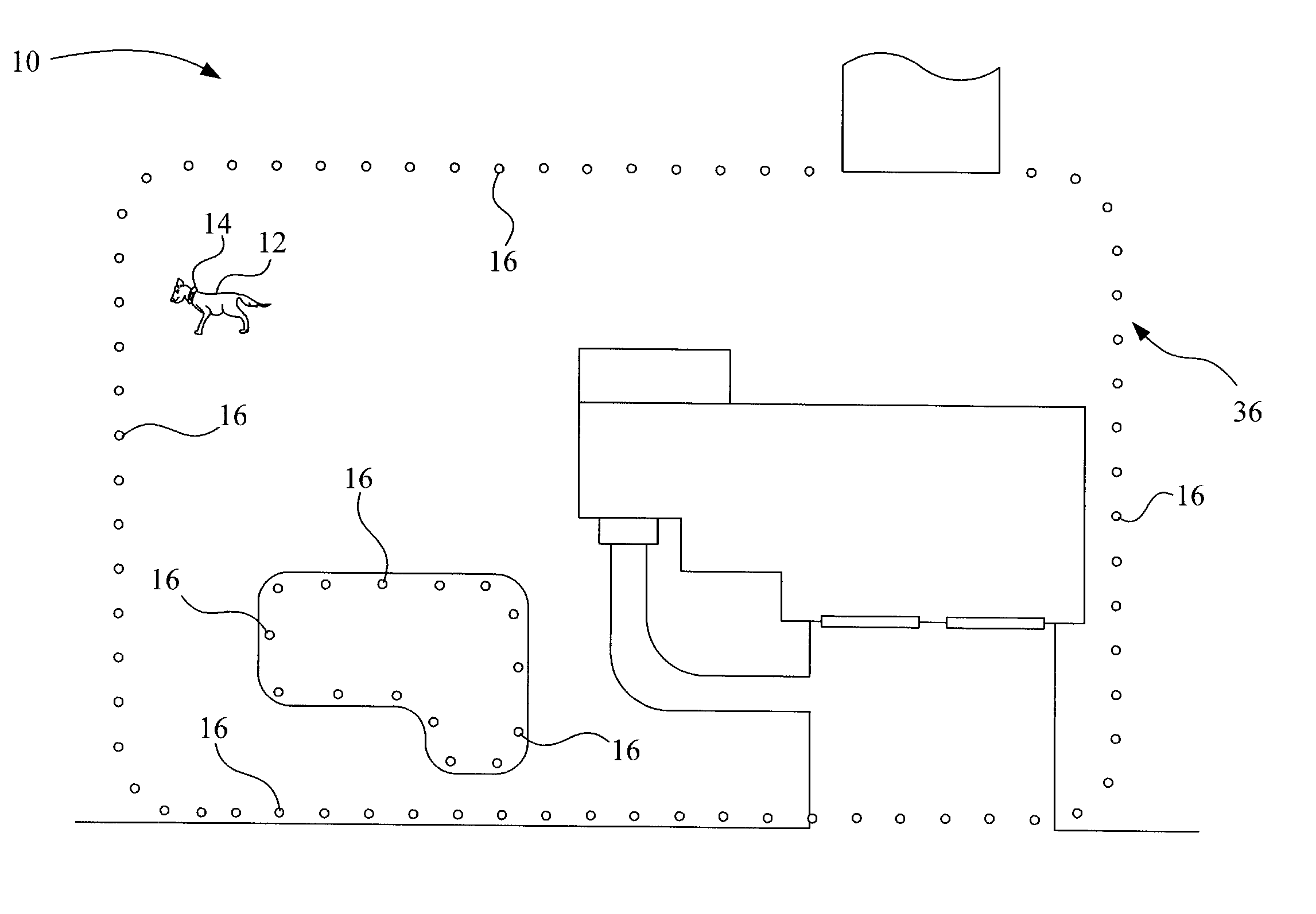
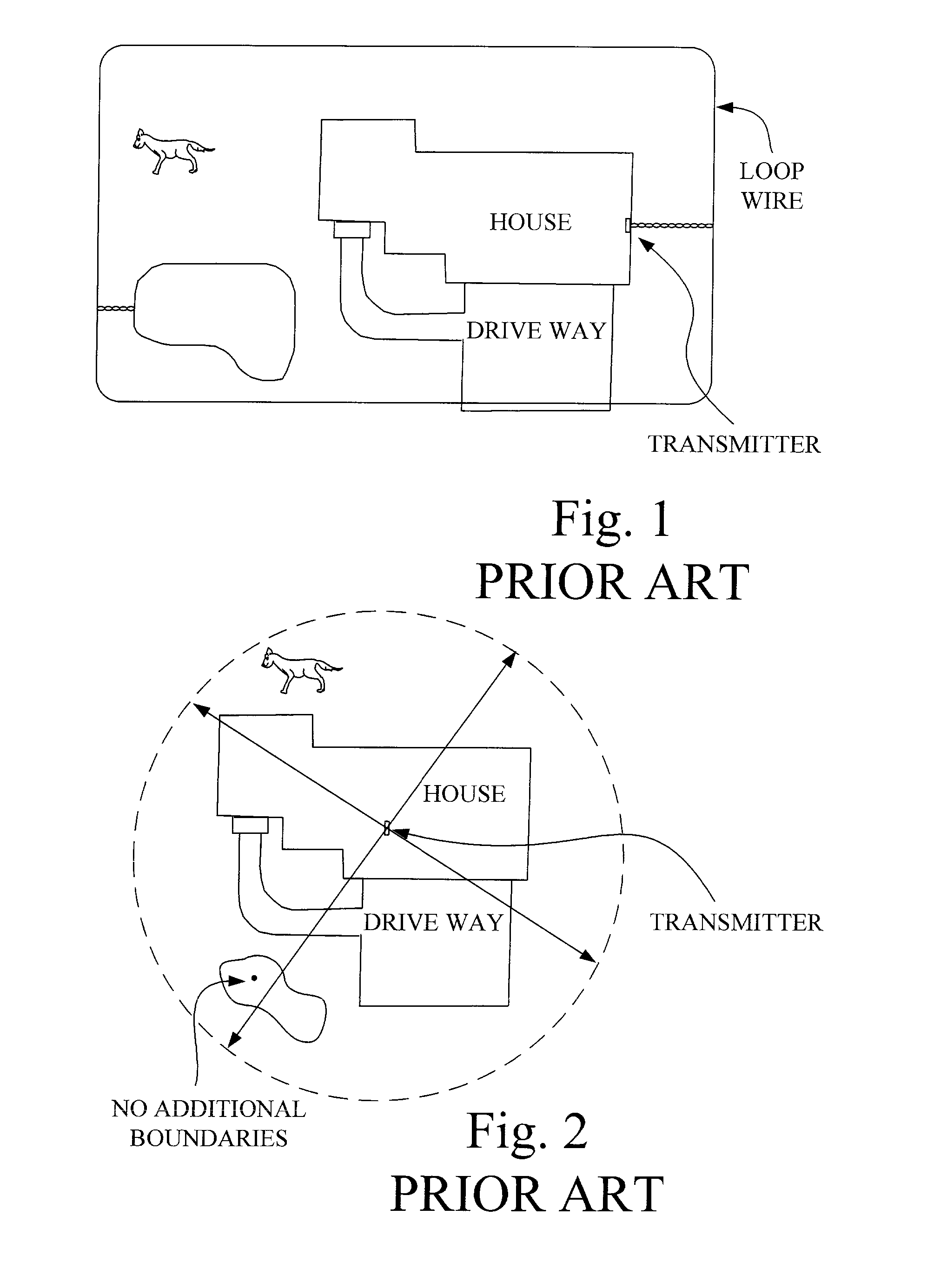
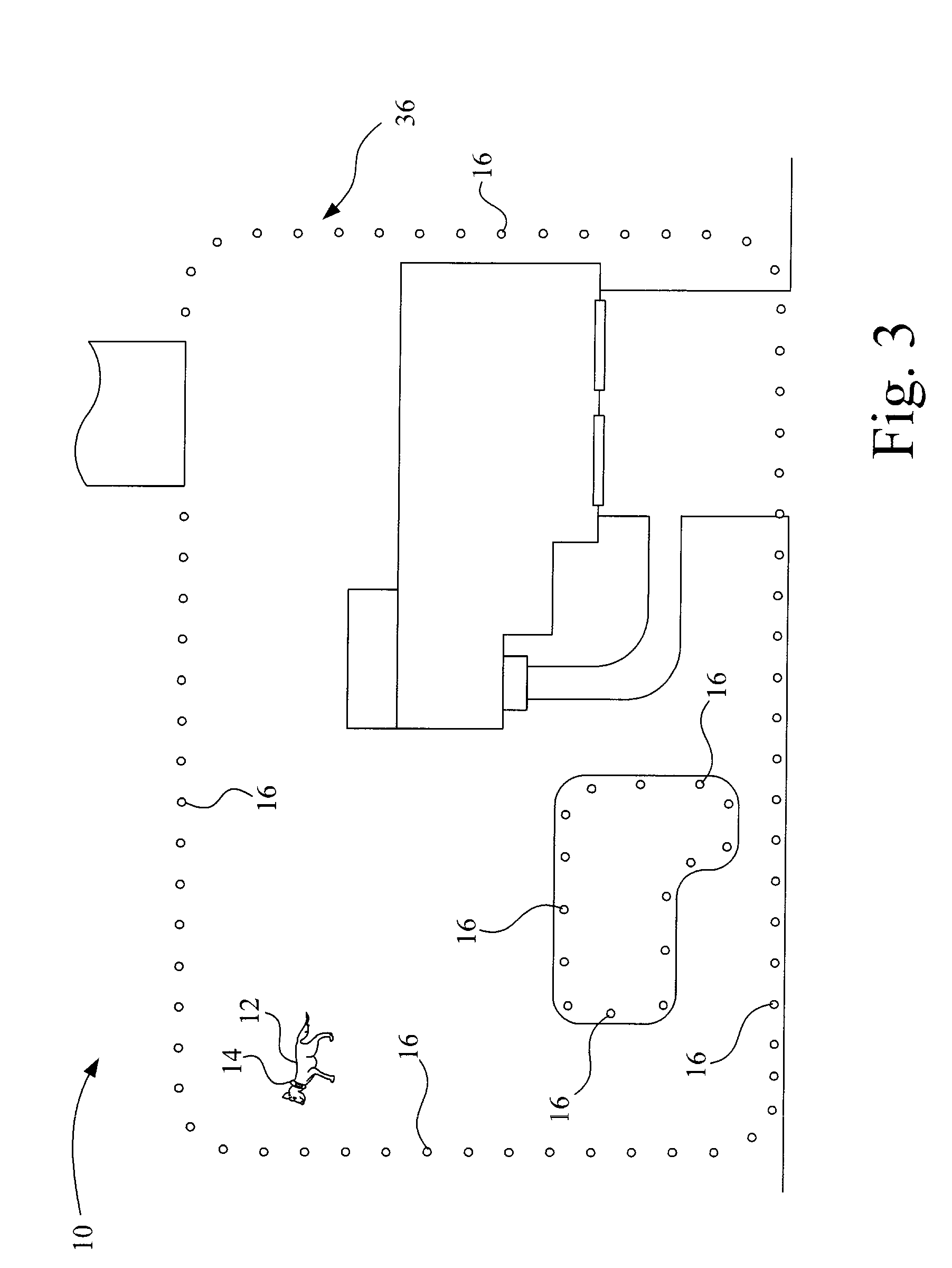
[0022] Referring now to the drawings, and more particularly to FIG. 3, there is shown a confinement system 10 for an animal 12 having a behavior modification device 14, also known as a collar system 14 around the neck of animal 12. Multiple receiver / transmitters 16, also known as transponders 16, are spaced about a border 36. Transponders 16 are placed approximately a predetermined distance apart along border 36, the predetermined distance may be, for example, 5 feet, or 7 feet. Transponders 16 are shaped similar to a golf tee and are simply pressed into the ground. Border 36 is established by placing transponders 16 in a spaced apart manner substantially...


PUM


Abstract

A confinement system including a plurality of receiver/transmitters spaced along a border and a behavior modification device. The behavior modification device includes a receiver and a stimulus device. The receiver receives a signal from at least one of the plurality of receiver/transmitters. The stimulus device delivers a stimulus if the major modification device is within a predetermined distance of the border.

Description

CROSS REFERENCE TO RELATED APPLICATIONS [0001] This is a non-provisional application based upon U.S. provisional patent application Ser. No. 60 / 761,705, entitled “ELECTRONIC PET CONFINEMENT SYSTEM”, filed Jan. 24, 2006.BACKGROUND OF THE INVENTION [0002] 1. Field of the Invention [0003] The present invention relates to an animal confinement system, and, more particularly, to a wireless confinement system for an animal. [0004] 2. Description of the Related Art [0005] Pet confinement systems often include a radio frequency transmitter having a wire loop for transmitting the radio frequency signal, as illustrated in FIG. 1. The wire loop antenna roughly defines the boundary to which the animal is to be confined. The animal wears a receiving unit that is attached to a collar worn around the animal's neck. The animal gets within a predetermined distance of the wire loop antenna, the receiver unit detects the radio frequency signal transmitted from the loop antenna, where upon a correcting...

Claims


Application Information

Patent Timeline
IPC IPC(8): A01K15/04
CPCA01K15/023
Inventor WESTRICK, MICHAEL
Owner WESTRICK MICHAEL
Why Eureka
Try Eureka