Device for Controling Electrically Actuable Valves in Different Operating Modes
- Summary
- Abstract
- Description
- Claims
- Application Information
AI Technical Summary
Benefits of technology
Problems solved by technology
Method used
Image

Examples
Embodiment Construction
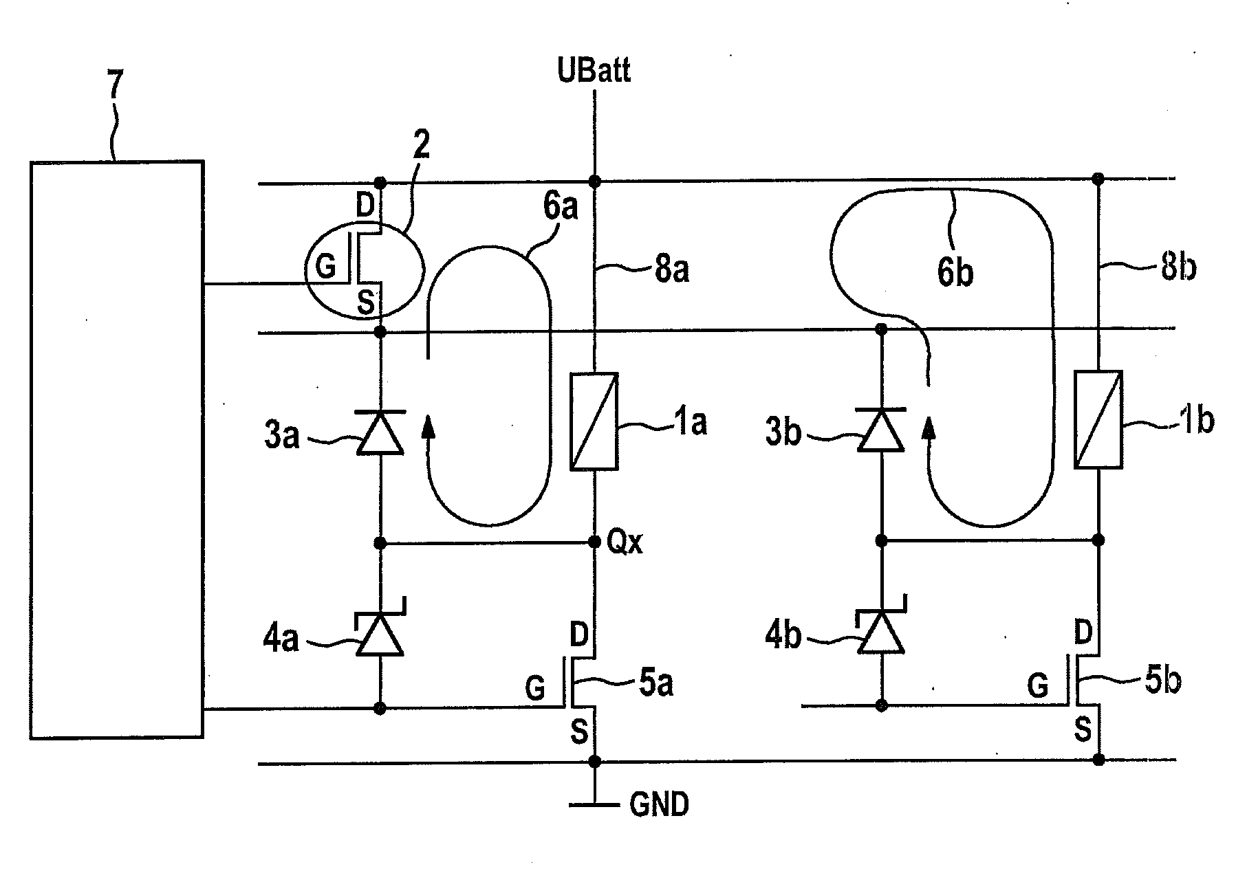
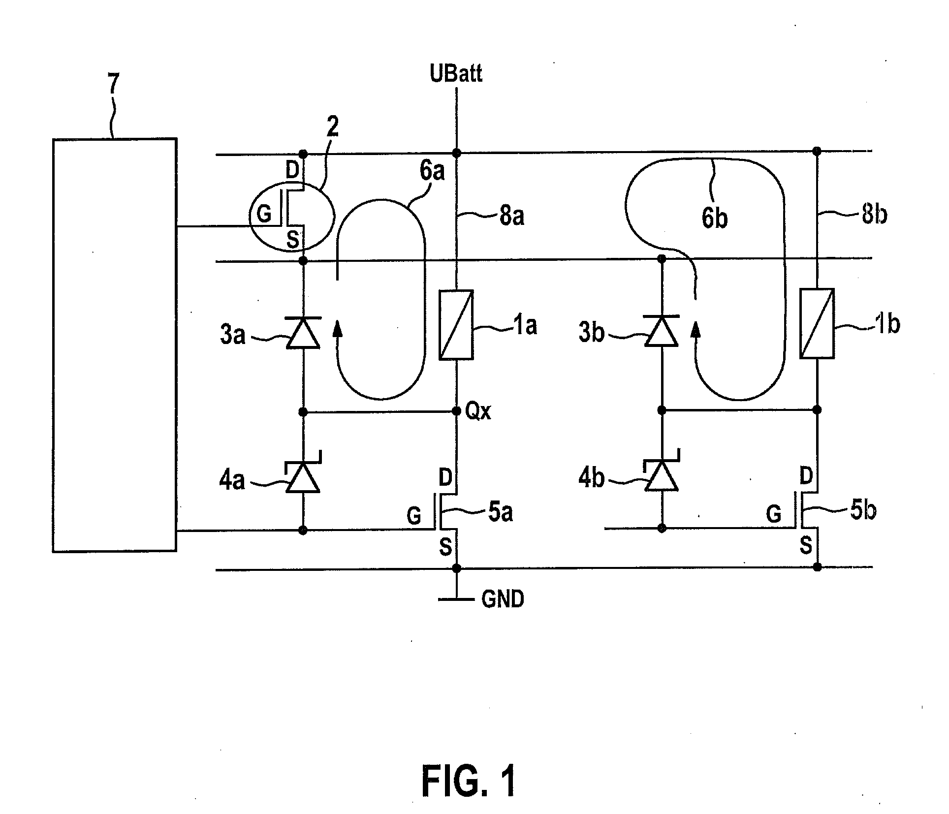
[0020]FIG. 1 shows a control circuit for two electrically actuable valves, each of which has a valve coil 1a, 1b. With the aid of the control circuit, the valves are optionally controllable in the switching operation or in the PWM operation.
[0021]A main switch 5a and 5b, by which the current flowing through valve coils 1a, 1b is adjusted, is connected in main current path 8a, 8b of the valves. Main switches 5a, 5b are situated on the ground side in relation to valve coils 1a, 1b, and therefore are also referred to as low-side switches. They are realized as MOS transistors in this exemplary embodiment. The drain terminal (D) is connected to the ground-side terminal of valve coil 1a or 1b, and the source terminal (S) is connected to ground (GND). The control inputs (G) of main switches 5a, 5b are connected to a control device 7 in each case, which controls them as a function of the “switching operation” or “PWM operation” operating mode.
[0022]In the PMW operation, main switches 5a, 5b...
PUM
 Abstract
Description
Claims
Application Information
 - R&D Engineer
- R&D Manager
- IP Professional
- Industry Leading Data Capabilities
- Powerful AI technology
- Patent DNA Extraction
Browse by: Latest US Patents, China's latest patents, Technical Efficacy Thesaurus, Application Domain, Technology Topic.
© 2024 PatSnap. All rights reserved.Legal|Privacy policy|Modern Slavery Act Transparency Statement|Sitemap